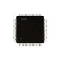
SAA7324H NXP Semiconductors, SAA7324H Datasheet - Page 24

SAA7324H
Manufacturer Part Number
SAA7324H
Description
Manufacturer
NXP Semiconductors
Datasheet
1.SAA7324H.pdf
(68 pages)
Specifications of SAA7324H
Operating Temperature (max)
70C
Operating Temperature Classification
Commercial
Mounting
Surface Mount
Pin Count
64
Lead Free Status / Rohs Status
Compliant
Available stocks
Company
Part Number
Manufacturer
Quantity
Price
Company:
Part Number:
SAA7324H
Manufacturer:
PHILIPS
Quantity:
84
Company:
Part Number:
SAA7324H/M2B,557
Manufacturer:
NXP Semiconductors
Quantity:
10 000
Company:
Part Number:
SAA7324H/T/M2B
Manufacturer:
NXP
Quantity:
5 000
Part Number:
SAA7324H/T/M2B
Manufacturer:
PHILIPS/飞利浦
Quantity:
20 000
Philips Semiconductors
7.13.1.4
In the CDV motor mode, the FIFO position will be put in
pulse-width modulated form on the MOTO1 pin [carrier
frequency (300
The PLL frequency signal will be put in pulse-density
modulated form (carrier frequency 4.23
MOTO2 pin. The integrated motor servo is disabled in this
mode.
The PWM signal on MOTO1 corresponds to a total
memory space of 20 frames, therefore the nominal FIFO
position (half full) will result in a PWM output of 60%.
In the lock-to-disc (CAV) mode the CDV motor mode is the
only mode that can be used to control the motor.
7.13.2
The operating modes of the motor servo is controlled by
decoder register 1 (see Table 11).
In the SAA7324 decoder there is an anti-windup mode for
the motor servo, selected via decoder register 1. When the
anti-windup mode is activated the motor servo integrator
will hold if the motor output saturates.
2000 Jun 26
Digital servo processor and Compact Disc
decoder with integrated DAC (CD10 II)
S
PINDLE MOTOR OPERATING MODES
CDV/CAV output mode
d) Hz], where ‘d’ is the disc speed factor.
MOTO1
V4
Fig.18 Motor 4-line PWM mode application diagram.
n MHz) on the
10
V SS
24
M
+
7.13.2.1
In start mode 1, start mode 2, stop mode 1 and stop
mode 2, a fixed positive or negative voltage is applied to
the motor. This voltage can be programmed as a
percentage of the maximum possible voltage, via
register 6, to limit current drain during start and stop.
The following power limits are possible:
7.13.3
The gain and crossover frequencies of the motor control
loop can be programmed via decoder registers 4 and 5.
The following parameter values are possible:
It should be noted that the crossover frequencies f
are scaled with the overspeed factor ‘n’ whereas the gains
are not.
100% (no power limit), 75%, 50%, or 37% of maximum.
Gains: 3.2, 4.0, 6.4, 8.0, 12.8, 16, 25.6 and 32
Crossover frequency f
1.4
Crossover frequency f
3.42
100 nF
n Hz and 2.8
L
n Hz.
OOP CHARACTERISTICS
Power limit
MGA364 - 2
n Hz
MOTO2
V5
4
3
: 0.5
: 0.85
n Hz, 0.7
n Hz, 1.71
Product specification
SAA7324
n Hz,
n Hz and
3
and f
4


