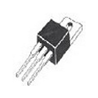
IXGP 12N60CSN IXYS, IXGP 12N60CSN Datasheet - Page 2

IXGP 12N60CSN
Manufacturer Part Number
IXGP 12N60CSN
Description
Manufacturer
IXYS
Datasheet
1.IXGP_12N60CSN.pdf
(4 pages)
Specifications of IXGP 12N60CSN
Channel Type
N
Configuration
Single
Collector-emitter Voltage
600V
Collector Current (dc) (max)
24A
Gate To Emitter Voltage (max)
±20V
Package Type
TO-220AB
Pin Count
3 +Tab
Mounting
Through Hole
Operating Temperature (min)
-55C
Operating Temperature (max)
150C
Operating Temperature Classification
Military
Lead Free Status / Rohs Status
Compliant
Symbol
(T
g
C
C
C
Q
Q
Q
t
t
t
t
E
t
t
E
t
t
E
R
R
IXYS reserves the right to change limits, test conditions, and dimensions.
d(on)
d(off)
fi
d(on)
d(off)
fi
ri
ri
fs
off
on
off
ies
oes
res
thJC
thCK
g
ge
gc
J
= 25 C, unless otherwise specified)
Test Conditions
I
Pulse test, t
V
I
Inductive load, T
I
V
Remarks: Switching times may
increase for V
higher T
C
C
C
Inductive load, T
I
V
Remarks: Switching times may
increase for V
higher T
CE
C
CE
CE
= I
= I
= 25 V, V
= I
= 0.8 V
= I
= 0.8 V
C90
C90
C90
C90
; V
, V
J
J
, V
or increased R
, V
or increased R
(Dimensions in inches and mm)
CE
GE
CES
GE
Min. Recommended Footprint
CES
GE
GE
= 10 V,
= 15 V, V
CE
, R
= 15 V, L = 300 H
300 s, duty cycle
CE
= 0 V, f = 1 MHz
, R
= 15 V, L = 300 H
(Clamp) > 0.8 V
G
(Clamp) > 0.8 V
G
J
J
= R
= R
= 125 C
= 25 C
off
CE
off
= 18
G
= 18
= 0.5 V
G
CES
CES
CES
,
2 %
,
Min.
Characteristic Values
7
Typ.
0.09
0.15
0.27
0.25
IXGA12N60C
860
11
32
10
10
20
20
60
55
20
20
85
85
64
15
0.60
1.25
Max.
180
180
K/W
K/W
mJ
mJ
mJ
nC
nC
nC
pF
pF
pF
n s
n s
n s
n s
n s
n s
n s
n s
S
Pins: 1 - Gate
TO-220 AB Dimensions
TO-263 AA Outline
IXGP12N60C
3 - Emitter
2 - Collector
4 - Collector
Bottom Side


