IXGP 12N60CSN IXYS, IXGP 12N60CSN Datasheet
Home Discrete Semiconductor Products IGBTs - Single IXGP 12N60CSN
Manufacturer Part Number
IXGP 12N60CSN
Specifications of IXGP 12N60CSN
Channel Type
N
Configuration
Single
Collector-emitter Voltage
600V
Collector Current (dc) (max)
24A
Gate To Emitter Voltage (max)
±20V
Package Type
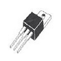
TO-220AB
Pin Count
3 +Tab
Mounting
Through Hole
Operating Temperature (min)
-55C
Operating Temperature (max)
150C
Operating Temperature Classification
Military
Lead Free Status / Rohs Status
Compliant
HiPerFAST
Symbol
V
V
V
V
I
I
I
SSOA
(RBSOA)
P
T
T
T
M
Weight
Maximum lead temperature for soldering
1.6 mm (0.062 in.) from case for 10 s
Symbol
(T
BV
V
I
I
V
© 2002 IXYS All rights reserved
CM
C25
C90
CES
GES
J
JM
stg
CGR
GEM
C
GE(th)
CE(sat)
CES
GES
d
J
CES
= 25 C, unless otherwise specified)
Test Conditions
T
T
Continuous
Transient
T
T
T
V
Clamped inductive load, L = 300 H
T
Mounting torque with screw M3
Mounting torque with screw M3.5
Test Conditions
I
I
V
V
V
I
C
C
C
J
J
C
C
C
GE
C
GE
CE
CE
= 250 A, V
= 250 A, V
= 0 V
= 0 V, V
= I
= 0.8, V
= 25 C to 150 C
= 25 C to 150 C; R
= 25 C
= 90 C
= 25 C, 1 ms
= 15 V, T
= 25 C
CE90
, V
GE
CES
TM
GE
VJ
= 20 V
= 15
GE
GE
= 125 C, R
= 0 V
= V
IGBT
GE
GE
= 1 M
G
= 33
T
T
J
J
= 25 C
= 125 C
Min.
600
Maximum Ratings
2.5
IXGA 12N60C
IXGP 12N60C
Characteristic Values
-55 ... +150
-55 ... +150
@ 0.8 V
Typ.
2.1
I
CM
0.45/4 Nm/lb.in.
0.55/5 Nm/lb.in.
= 24
600
600
100
150
300
20
30
24
12
48
CES
4
Max.
200
100
5.0
2.7
1
mA
nA
W
V
C
C
C
C
A
V
V
V
V
A
A
A
A
g
V
V
Features
•
•
•
•
Applications
•
•
•
•
•
Advantages
•
•
Very high freqency IGBT
New generation HDMOS
International standard package
JEDEC TO-220AB and TO-263AA
High peak current handling capability
TO-263 AA (IXGA)
PFC circuits
AC motor speed control
DC servo & robot drives
Switch-mode and resonant-mode
power supplies
High power audio amplifiers
Fast switching speed
High power density
TO-220 AB
(IXGP)
V
V
I
t
G = Gate
E = Emitter
C25
fi(typ)
CE(sat)
CES
G
C
G
E
= 600
=
= 2.7
=
E
C
TAB = Collector
24
55 ns
= Collector
97534B (2/02)
TM
C (tab)
V
A
V
process
Related parts for IXGP 12N60CSN
IXGP 12N60CSN Summary of contents
... 250 GE(th 0.8, V CES CE CES GES CE(sat) C CE90 GE © 2002 IXYS All rights reserved IXGA 12N60C IXGP 12N60C Maximum Ratings 600 = 1 M 600 0.8 V CES 100 -55 ... +150 150 -55 ... +150 0.45/4 Nm/lb.in. 0.55/5 Nm/lb.in. 4 300 Characteristic Values Min. Typ. Max. 600 2.5 5 ...
... Remarks: Switching times may t fi increase for V (Clamp) > 0 higher T or increased off R thJC R thCK Min. Recommended Footprint (Dimensions in inches and mm) IXYS reserves the right to change limits, test conditions, and dimensions. IXGA12N60C Characteristic Values Min. Typ. Max 860 0 CES 10 20 ...
... V - Volts CE Fig. 3. Saturation Voltage Characteristics 10V 125° 25° Volts GE Fig. 5. Saturation Voltage Characteristics © 2002 IXYS All rights reserved IXGA12N60C 100 11V Fig. 2. Extended Output Characteristics 1.75 11V 1.50 1.25 9V 1.00 7V 0. Fig. 4. Temperature Dependence of V 1000 100 Fig. 6. Junction Capacitance Curves ...
... Fig. 9. Gate Charge 1 D=0.5 D=0.2 D=0.1 0.1 D=0.05 D=0.02 D=0.01 0.01 Single pulse 0.001 0.00001 0.0001 Fig. 11. Transient Thermal Resistance IXYS reserves the right to change limits, test conditions, and dimensions. IXGA12N60C 1 0 Fig. 8. Dependence of E OFF C 100 ...
Related keywords
IXGP 12N60CSN datasheet IXGP 12N60CSN data sheet IXGP 12N60CSN pdf datasheet IXGP 12N60CSN component IXGP 12N60CSN part IXGP 12N60CSN distributor IXGP 12N60CSN RoHS IXGP 12N60CSN datasheet download