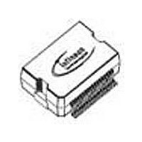
TLE6232GPNT Infineon Technologies, TLE6232GPNT Datasheet - Page 7

TLE6232GPNT
Manufacturer Part Number
TLE6232GPNT
Description
Manufacturer
Infineon Technologies
Datasheet
1.TLE6232GPNT.pdf
(19 pages)
Specifications of TLE6232GPNT
Switch Type
Low Side
Power Switch Family
TLE6232
Input Voltage
-0.3 to 7V
Power Switch On Resistance
250mOhm
Output Current
1.5A
Number Of Outputs
6
Mounting
Surface Mount
Supply Current
10mA
Package Type
DSO
Operating Temperature (min)
-40C
Operating Temperature (max)
150C
Operating Temperature Classification
Automotive
Pin Count
38
Power Dissipation
3300W
Lead Free Status / Rohs Status
Compliant
Description of the Power Stages
4 low side power switches for nominal currents up to 3A (power stages OUT1 to OUT4). Con-
trol is possible by input pins or via SPI. For T
switches is below 500mΩ.
2 low side power switches for nominal currents up to 1.5A (power stages OUT5 and OUT6).
Control is possible by input pins or via SPI. For T
switches is below 1Ω.
In order to increase the switching current or to reduce the power dissipation parallel connec-
tion of power stages is possible.
Each of the 6 output stages is equipped with an own zener clamp, that limits the output volt-
age to a maximum of 60V. The outputs are provided with a current limitation set to a minimum
of 1.5A resp. 3A. Each power stage is equipped with an own temperature sensor.
Each output is protected by embedded protection functions
circuit to U
(early warning). If this operation leads to an overtemperature condition, a second protection
level (about 170°C) will change the output into a low duty cycle PWM (selective thermal shut-
down with restart) to prevent critical chip temperatures.
The following faults can be detected (individually for each output):
- short to UBatt:
- short to ground:
- open load:
- overtemperature: (OT) will only be detected when switches are
The fault conditions SCB, SCG and OL will not be stored until an integrated filtering time is
expired (please note for PWM application). If, at one output, several errors occur in a se-
quence, always the last detected error will be stored (with filtering time). All fault conditions are
encoded in two bits per switch and are stored in the corresponding SPI registers. Additionally
there are two central diagnostic bits: one especially for overtemperature (latched result of an
OR-operation out of the 6 signals of the temperature sensor) and one for fault occurrence at
any output. A fault that has been detected and stored in the fault register must not be replaced
by o.k.-state (11) unless it is read out by the RD_DIAG command sent by the microcontroller
or an internal or external reset has been applied. I.e. the fault register will be cleared only by
the RD_DIAG command.
PRG - Program pin.
If the parallel input pins are not connected (independent of high or low activity) it is guaranteed
that the channels 1 to 6 are switched OFF.
PRG pin itself is internally pulled down when it is not connected.
5)
normal operation or permanently.
V1
The integrated protection functions prevent an IC destruction under fault conditions and may not be used in
Batt
the current is internally limited and the corresponding bit combination is set
(SCB/overload) can be detected when switches are
(SCG) can be detected when switches are
(OL) can be detected when switches are
PRG = High (V
PRG = Low (GND): Parallel inputs Channel 1 to 6 are low active.
S
):
Page
Parallel inputs Channel 1 to 6 are high active
J
= 150°C the on-resistance of the power
J
= 150°C the on-resistance of the power
7
5)
. In case of overload or short-
Data Sheet TLE 6232 GP
On state
Off state
Off state
On state
24.Jan. 2002


