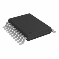
DAC8562FRU Analog Devices Inc, DAC8562FRU Datasheet - Page 13

DAC8562FRU
Manufacturer Part Number
DAC8562FRU
Description
IC DAC 12BIT PARALLEL 5V 20TSSOP
Manufacturer
Analog Devices Inc
Datasheet
1.DAC8562FSZ.pdf
(16 pages)
Specifications of DAC8562FRU
Rohs Status
RoHS non-compliant
Settling Time
16µs
Number Of Bits
12
Data Interface
Parallel
Number Of Converters
1
Voltage Supply Source
Single Supply
Power Dissipation (max)
30mW
Operating Temperature
-40°C ~ 85°C
Mounting Type
Surface Mount
Package / Case
20-TSSOP
REV. A
To compensate for the SSM2018’s gain constant temperature
coefficient of –3300 ppm/ C, a 1 k , temperature-sensitive
resistor (R7) manufactured by the Precision Resistor Com-
pany with a temperature coefficient of +3500 ppm/ C is used.
A C
yields a click-free change in the audio channel attenuation. Sym-
metry and offset trimming details of the VCA can be found in
the SSM2018 data sheet.
Information regarding the PT146 1 k “Compensator” can be
obtained by contacting:
Precision Resistor Company, Incorporated
10601 75th Street North
Largo, FL 34647
(813) 541-5771
A High-Compliance, Digitally Controlled Precision Current
Source
The circuit in Figure 38 shows the DAC8562 controlling a
high-compliance, precision current source using an AMP05 in-
strumentation amplifier. The AMP05’s reference pin becomes
the input, and the “old” inputs now monitor the voltage across a
precision current sense resistor, R
so the transfer function is given by the following equation:
If R
with a 1 V input. Therefore, each DAC LSB corresponds to
2.4 A. If a bipolar output current is required, then the circuit
in Figure 33 can be modified to drive the AMP05’s reference
pin with a 1 V input signal.
Potentiometer P1 trims the output current to zero with the in-
put at 0 V. Fine gain adjustment can be accomplished by adjust-
ing R1 or R2.
A Digitally Programmable Window Detector
A digitally programmable, upper/lower limit detector using two
DAC8562s is shown in Figure 39. The required upper and
CS
CON
equals 100 , the output current is limited to +10 mA
of 1 F provides a control transition time of 1 ms which
HDAC/LDAC
74HC05
CLR
I
1/6
OUT
2
1
+5V
1k
CS
V
R
. Voltage gain is set to unity,
IN
CS
DATA
Figure 39. A Digitally Programmable Window Detector
16
15
16
15
DGND AGND
DGND AGND
DAC-8562
DAC-8562
10
10
+5V
+5V
20
20
12
12
0.1µF
0.1µF
13
13
–13–
V
IN
lower limits for the test are loaded into each DAC individually
by controlling HDAC/LDAC. If a signal at the test input is not
within the programmed limits, the output will indicate a logic
zero which will turn the red LED on.
C1, C2 = 1/4 CMP-404
4
5
7
6
100k
Figure 38. A High-Compliance, Digitally Controlled
Precision Current Source
R1
REF-02
C1
C2
+5V
12
3
+15V
4
2
17
18
2
1
0.1µF
0.1µF
1
4
2
CLR
6
CE
100k
DATA
AMP-05
P1
7
5k
+5V
R2
16
15
5
PASS/FAIL
RED LED
R1
604
–15V
11
3
6
DGND
T1
74HC05
DAC-8562
10
0.1µF
1/6
9
+15V
12
20
4
0.1µF
AGND
+5V
8
12
0.1µF
R2
604
GREEN LED
10
13
T1
R
100
CS
R3
3k
DAC8562
0mA
2.4µA/ LSB
R4
1k
I
OUT
10mA


