1274584-1 TE Connectivity, 1274584-1 Datasheet - Page 3
1274584-1
Manufacturer Part Number
1274584-1
Description
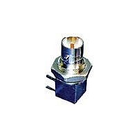
RF/COAXIAL BNC BHD PLUG R/A 75OHM SOLDER
Manufacturer
TE Connectivity
Specifications of 1274584-1
Connector Type
BNC Coaxial
Body Style
Right Angle Bulkhead Plug
Coaxial Termination
Solder
Impedance
75ohm
Contact Material
Phosphor Bronze
Contact Plating
Gold
Frequency Max
2GHz
Rohs Compliant
Yes
Product Type
Connector - RF
Gender
Jack
Stacked
No
Pcb Mounting Orientation
Right Angle
Grade
Commercial
Pcb Mount Retention
Without
Body Material
Brass
Sealed
No
Isolated
No
Dielectric Material
PTFE
Number Of Ports
1
Solder Terminal
With
Surface Mountable
No
Panel Mount Retention
With
Panel Mount Retention Type
Bulkhead
Panel Attachment Style
Rear Mount
Connector Impedance (?)
75
Insulation Resistance (m?)
1,000
Frequency
DC - 2 GHz
Pcb Height (mm [in])
8.53 [0.336]
Hardware Included
No
Body Plating
Nickel
Polarized
No
Pcb Tail Length (mm [in])
4.00 [0.157]
Center Contact Material
Phosphor Bronze
Center Contact Plating
Gold
Connector Style
Jack
Government/industry Qualification
No
Rohs/elv Compliance
RoHS compliant, ELV compliant
Lead Free Solder Processes
Wave solder capable to 240°C, Wave solder capable to 260°C, Wave solder capable to 265°C, Reflow solder capable to 245°C, Reflow solder capable to 260°C, Pin-in-Paste capable to 245°C, Pin-in-Paste capable to 260°C
Rohs/elv Compliance History
Always was RoHS compliant
Applies To
Printed Circuit Board
For Use With
Mini BNC Connector


Rev C
W ithstanding voltage.
Vibration, random .
Mechanical shock.
Durability.
Mating force.
Unm ating force.
Term ination tensile strength.
Therm al shock.
Hum idity, steady state.
Tem perature life.
Test Description
1 m inute hold with no breakdown or
flashover.
No discontinuities of 1 m icrosecond
or longer duration.
See Note.
No discontinuities of 1 m icrosecond
or longer duration.
See Note.
See Note.
31 N [7 lbf] m axim um .
4 N [1 lbf] m inim um .
89 N [20 lbf].
See Note.
See Note.
See Note.
Figure 1 (continued)
ENVIRONMENTAL
MECHANICAL
Requirem ent
EIA-364-13.
EIA-364-20, Condition I.
1000 volts AC at sea level.
Test between adjacent contacts of
unm ated specim ens.
EIA-364-28, Test Condition VII,
Condition D.
Subject m ated specim ens to 3.10
G's rm s between 20-500 Hz. 15
m inutes in each of 3 m utually
perpendicular planes.
EIA-364-27, Method H.
Subject m ated specim ens to 30 G's
half-sine shock pulses of 11
m illiseconds duration. 3 shocks in
each direction applied along 3
m utually perpendicular planes, 18
total shocks.
EIA-364-9.
Mate and unm ate specim ens for
500 cycles at a m axim um rate of
600 cycles per hour.
Measure force necessary to
engage coupling m echanism at a
m axim um rate of 12.7 m m [.5 in]
per m inute.
EIA-364-13.
Measure force necessary to
disengage coupling m echanism at
a m axim um rate of 12.7 m m [.5 in]
per m inute.
EIA-364-8.
Apply specified load at a rate of 25
± 6 m m [.984 ± .24 in] per m inute.
EIA-364-32.
Subject unm ated specim ens to 5
cycles between -40 and 85°C.
EIA-364-31, Method II, Condition C.
Subject unm ated specim ens to
40°C and 90 to 95% RH for 504
hours.
EIA-364-17, Method A, Test
Condition 3, Test Tim e Condition D.
Subject m ated specim ens to 85°C
for 1000 hours.
Procedure
108-2159
3 of 5
Related parts for 1274584-1
Image
Part Number
Description
Manufacturer
Datasheet
Request
R

Part Number:
Description:
CONN SMP RCPT STR RG-405 SOLDER
Manufacturer:
Emerson Network Power

Part Number:
Description:
CONN SMP RCPT STR M17/151 SOLDER
Manufacturer:
Emerson Network Power

Part Number:
Description:
CONN SMP RCPT MALE END LANCH SMD
Manufacturer:
Emerson Network Power

Part Number:
Description:
CONN SMP RCPT MALE END LANCH SMD
Manufacturer:
Emerson Network Power

Part Number:
Description:
CONN SMP RCPT MALE STR PC MOUNT
Manufacturer:
Emerson Network Power

Part Number:
Description:
High Speed / Modular Connectors 30P HEADER ASSY
Manufacturer:
TE Connectivity
Datasheet:

Part Number:
Description:
High Speed / Modular Connectors REC 6X005P R/A LT B-PLANE HS3
Manufacturer:
TE Connectivity
Datasheet:

Part Number:
Description:
High Speed / Modular Connectors 2MM HM RCPT 50P R/A AU
Manufacturer:
TE Connectivity
Datasheet:

Part Number:
Description:
High Speed / Modular Connectors 2MM HM RCPT 50P R/A AU
Manufacturer:
TE Connectivity
Datasheet:


Part Number:
Description:
Manufacturer:
TE Connectivity
Datasheet:


Part Number:
Description:
Manufacturer:
TE Connectivity
Datasheet:

Part Number:
Description:
Manufacturer:
TE Connectivity
Datasheet:

Part Number:
Description:
Manufacturer:
TE Connectivity
Datasheet: