1-1734592-4 TE Connectivity, 1-1734592-4 Datasheet - Page 2
1-1734592-4
Manufacturer Part Number
1-1734592-4
Description
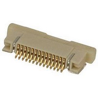
FFC/FPC CONNECTOR, RECEPTACLE 14POS 1ROW
Manufacturer
TE Connectivity
Specifications of 1-1734592-4
Gender
Receptacle
Pitch Spacing
0.5mm
No. Of Contacts
14
No. Of Rows
1
Contact Plating
Gold
Ffc/fpc Thickness
0.3mm
Contact Termination
Surface Mount Horizontal
Rohs Compliant
Yes
Termination Method To Pc Board
Surface Mount
Pcb Mounting Orientation
Right Angle
Pcb Mount Alignment
Without
Pcb Mount Retention
With
Actuator Type
Stuffer
Shrouded
Yes
Sealed
No
Strain Relief
Without
Contact Current Rating, Max (a)
0.5
Operating Voltage Reference
AC
Operating Voltage (vac)
250
Shielded
No
Tail Orientation
In-line
Profile Height (y-axis) (mm [in])
2.05 [0.080]
Centerline (mm [in])
0.50 [0.0197]
Number Of Positions
14
Selectively Loaded
No
Pcb Mount Retention Type
Solder Pads
Length (x-axis) (mm [in])
12.43 [0.4893]
Width (z-axis) (mm [in])
5.10 [0.200]
Contact Plating, Mating Area, Material
Gold
Contact Plating, Mating Area, Thickness (µm [?in])
0.025 [0.984]
Tail Plating Material
Gold
Tail Plating, Thickness (µm [?in])
0.025 [0.984]
Contact Design
Single Beam
Housing Material
Liquid Crystal Polymer (LCP)
Contact Mating Location
Bottom
Flex Cable Thickness (mm [in])
0.3 [0.012]
Housing Color
Ivory
Rohs/elv Compliance
RoHS compliant, ELV compliant
Lead Free Solder Processes
Reflow solder capable to 245°C, Reflow solder capable to 260°C
Rohs/elv Compliance History
Always was RoHS compliant
Circuit Identification Feature
Without
Operating Temperature (°c [°f])
-20 – +85 [-4 – +185]
Zif/non-zif
ZIF
Contact Transmits (typical Application)
Signal (Data)
Pick And Place Cover
Without
Packaging Method
Tape & Reel


Rev
1 Examination of Product
2 Contact Resistance
3
4
5
6
7
8
9
Insulation Resistance 100M Ohm Min.(Initial)
Dielectric
Withstanding
Resistance
Durability
Vibration
Physical Shock
Contact Retention
Force
Solder ability
The product shall be designed to meet the electrical, mechanical and environmental performance
requirements specified in Figure 1. All tests shall be performed at ambient environmental conditions per
AMP Specification 109-1TEST REQUIREMENTS AND PROCEDURES SUMMARY.
3.4.
3.5.
B
Test Item
Test Item
PERFOMANCE REQUEIREMENT AND TEST DESCRIPTION
TEST REQUIREMENTS AND PROCEDURES SUMMARY
35mΩ. Max.
50M Ohm Min. ( Final)
No creeping discharge or
flashover shall occur.
Current leakage:0.5mA MAX
See Note
No electrical discontinuity
greater than 1microsecond shall
occur.
See Note.
During and after each shock,
the contacts shell be no
discontinuity
greater then 1 microsecond.
250 gf min.
Wet solder coverage:95% Min.
Meets requirements of product
drawing. No physical damage.
MECHANICAL REQUIREMENT
ELECTRICAL REQUIREMENT
Requirement
Requirement
Figure 1(cont)
Subject mated contacts assembled in
housing to 20 mV DC Max open circuit at
100mA
MIL-STD-1344A Method 3002.1
Impressed voltage 500VDC. The insulation
resistance shall be measured between 10
adjacent 10 opposing contacts per FPC
connector.
MIL-STD-202F, Method 302
250VAC for 1minute
Test between adjacent circuits of unmated
connector.
MIL-STD-202F Method 301
Operation Speed: 25.4mm/minute
Durability Cycles:15 Cycles
(1)Test duration:3 hours along
Each of 3 mutually perpendicular
Plans(9hours totally)
(2)Test board thickness:1.6±0.02mm
MIL-STD-1344A,Method 2005
(1)Number of drops:3 drops in each of 3
mutually perpendicular planes
(2)Test board thickness:1.6±0.02mm
MIL-STD-202F,Method 213.
The test shall be performed 10PCS of each
different row of contacts the crosshead
speed should be less than 20mm per
minute.
Solder Temp.:235±5℃
Duration: 5±0.5sec.
MIL-STD-202F,Method 208D.
Visual inspection.
No physical damage
Procedure
Procedure
108-57523
2 of 4
Related parts for 1-1734592-4
Image
Part Number
Description
Manufacturer
Datasheet
Request
R

Part Number:
Description:
CONTACT, MCP 2.8, 17-13AWG
Manufacturer:
TE Connectivity
Datasheet:

Part Number:
Description:
250 FASTON IS
Manufacturer:
TE Connectivity
Datasheet:

Part Number:
Description:
MCP2,8 RECEPTACLE CONTACT
Manufacturer:
TE Connectivity
Datasheet:
Part Number:
Description:
CRIMP, RECEPTACLE
Manufacturer:
TE Connectivity
Datasheet:

Part Number:
Description:
Manufacturer:
TE Connectivity
Datasheet:

Part Number:
Description:
Manufacturer:
TE Connectivity
Datasheet:

Part Number:
Description:
Manufacturer:
TE Connectivity
Datasheet:

Part Number:
Description:
Manufacturer:
TE Connectivity
Datasheet:

Part Number:
Description:
Manufacturer:
TE Connectivity
Datasheet:

Part Number:
Description:
Manufacturer:
TE Connectivity
Datasheet:

Part Number:
Description:
Manufacturer:
TE Connectivity
Datasheet:

Part Number:
Description:
Manufacturer:
TE Connectivity
Datasheet:

Part Number:
Description:
Manufacturer:
TE Connectivity
Datasheet:

Part Number:
Description:
Manufacturer:
TE Connectivity
Datasheet:

Part Number:
Description:
Manufacturer:
TE Connectivity
Datasheet: