1-1734592-4 TE Connectivity, 1-1734592-4 Datasheet

FFC/FPC CONNECTOR, RECEPTACLE 14POS 1ROW

1-1734592-4

Manufacturer Part Number
1-1734592-4
Description
FFC/FPC CONNECTOR, RECEPTACLE 14POS 1ROW
Manufacturer
TE Connectivity
Datasheets

Specifications of 1-1734592-4

Gender
Receptacle
Pitch Spacing
0.5mm
No. Of Contacts
14
No. Of Rows
1
Contact Plating
Gold
Ffc/fpc Thickness
0.3mm
Contact Termination
Surface Mount Horizontal
Rohs Compliant
Yes
Termination Method To Pc Board
Surface Mount
Pcb Mounting Orientation
Right Angle
Pcb Mount Alignment
Without
Pcb Mount Retention
With
Actuator Type
Stuffer
Shrouded
Yes
Sealed
No
Strain Relief
Without
Contact Current Rating, Max (a)
0.5
Operating Voltage Reference
AC
Operating Voltage (vac)
250
Shielded
No
Tail Orientation
In-line
Profile Height (y-axis) (mm [in])
2.05 [0.080]
Centerline (mm [in])
0.50 [0.0197]
Number Of Positions
14
Selectively Loaded
No
Pcb Mount Retention Type
Solder Pads
Length (x-axis) (mm [in])
12.43 [0.4893]
Width (z-axis) (mm [in])
5.10 [0.200]
Contact Plating, Mating Area, Material
Gold
Contact Plating, Mating Area, Thickness (µm [?in])
0.025 [0.984]
Tail Plating Material
Gold
Tail Plating, Thickness (µm [?in])
0.025 [0.984]
Contact Design
Single Beam
Housing Material
Liquid Crystal Polymer (LCP)
Contact Mating Location
Bottom
Flex Cable Thickness (mm [in])
0.3 [0.012]
Housing Color
Ivory
Rohs/elv Compliance
RoHS compliant, ELV compliant
Lead Free Solder Processes
Reflow solder capable to 245°C, Reflow solder capable to 260°C
Rohs/elv Compliance History
Always was RoHS compliant
Circuit Identification Feature
Without
Operating Temperature (°c [°f])
-20 – +85 [-4 – +185]
Zif/non-zif
ZIF
Contact Transmits (typical Application)
Signal (Data)
Pick And Place Cover
Without
Packaging Method
Tape & Reel
1.
2.
3.
DR
Scott Chien
©2007 Tyco Electronics Corporation
Taipei, Taiwan
All International Rights Reserved.
1.1. CONTENTS
1.2.
The following TE documents form a part of this specification to the extent specified herein. Unless
otherwise specified, the latest edition of the document applies. In the event of conflict between the
requirements of this specification and the product drawing, the product drawing shall take precedence.
In the event of conflict between the requirements of this specification and the referenced documents,
this specification shall take precedence.
0.5mm Pitch Connector SMT Type.
specifications shall be used. All inspections shall be performed using the applicable inspection plan
and product drawing.
product drawing.
SCOPE
This specification covers the performance, tests and quality requirements for the FPC Connector,
When tests are performed on the subject product line, the procedures specified in TE 109 series
APPLICABLE DOCUMENT
2.1. TE SPECIFICATIONS
REQUIREMENTS
3.1. DESIGN AND CONSTRUCTION
Product shall be of the design, construction and physical dimensions specified on the applicable
3.2. MATERIALS
3.3.
QUALIFICATION
A. 109-1:General Requirements for the Test Specification
B. 109-197:TE Specification vs EIA and IEC Test Methods
C. 501-57598:Test Report
A. Housing:Thermoplastic, UL94V-0
B. Actuator:Thermoplastic, UL94 V-0
C. Contact:Copper Alloy, Tin Plating or Gold Plating over Nickel under-plating.
D. Hold Down:Copper Alloy, Tin Plating over Nickel under-plating.
A. Voltage: 250 VAC
B. Current: 0.5 A Max
C. Temperature: - 40 °C to 125 °C
RATINGS
* Trademark
│ Indicates change
Product
Specification
FPC Connector, 0.5mm Pitch, Connector SMT
Type
13-MAY-2010 William Kodama
For latest revision, visit our website at www.tycoelectronics.com\documents.
For Regional Customer Service, visit our website at www.tycoelectronics.com
DATE APVD
108-57523
09-Jun-2010 Rev B
13-MAY-2010
LOC DW
1 of 4
DATE

Related parts for 1-1734592-4

1-1734592-4 Summary of contents

Page 1

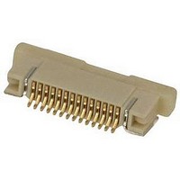
... This specification covers the performance, tests and quality requirements for the FPC Connector, 0.5mm Pitch Connector SMT Type. 1.2. QUALIFICATION When tests are performed on the subject product line, the procedures specified in TE 109 series specifications shall be used. All inspections shall be performed using the applicable inspection plan and product drawing. 2. ...

Page 2

... PERFOMANCE REQUEIREMENT AND TEST DESCRIPTION 3.4. The product shall be designed to meet the electrical, mechanical and environmental performance requirements specified in Figure 1. All tests shall be performed at ambient environmental conditions per AMP Specification 109-1TEST REQUIREMENTS AND PROCEDURES SUMMARY. TEST REQUIREMENTS AND PROCEDURES SUMMARY 3.5. ...

Page 3

... Within one hour after exposure MIL-STD-202F,Method 103B. Subject mated connectors to 35±2℃ and 5±1% salt(NaCl) for 48hrs. After test, rinse the sample with water and recondition the room temperature for 48hrs. MIL-STD-202F,Method 101D.1. condition B. ...

Page 4

... Physical Shock Contact Retention Force Solder ability Humidity Salt Spray Thermal Shock Temperature Life Resistance To Reflow Soldering Heat NOTE: (a)Numbers indicate sequence in which tests are performed. (b)Discontinuities shall not take place in this test group, during tests. Rev B Test Group ...

Related keywords