5749246-1 TE Connectivity, 5749246-1 Datasheet - Page 4
5749246-1
Manufacturer Part Number
5749246-1
Description
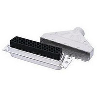
D SUB SHELL, RECEPTACLE, SIZE 2, STEEL
Manufacturer
TE Connectivity
Series
AMPLIMITE HDP-20r
Specifications of 5749246-1
Connector Type
D Sub
Connector Shell Size
2
Connector Body Material
Metal
Body Material
Steel
No. Of Contacts
15
Rohs Compliant
Yes
Product Type
Connector
Product Series
HDP-20 (Crimp Snap)
Mating Connector Lock
With
Mating Connector Lock Type
Slide Latches
Shell Size
2
Shell Type
Full Metal Shell
Grounding Indents
Without
Grade
Standard
Enclosure Material
PVC, Elastomer, Styrene polyolefin
Color
Black
Shell Material
Carbon Steel
Shield Material
Steel
Shielded
Yes
Number Of Positions
15
Pre-assembled
Yes
Cable Insulation Diameter (mm [in])
4.83 – 9.53 [0.190 – 0.375]
Shell Plating
Tin over Copper
Shield Plating
Tin over Copper
Insert Material
Nylon
Insert Flammability Rating
UL 94V-0
Locking Post Material
Brass
Locking Post Plating
Tin over matte Copper
Preloaded
No
Contact Size
20
Enclosure
With
Connector Style
Receptacle
Housing Material
Nylon
Ul Flammability Rating
UL 94V-0
Housing Color
Black
Rohs/elv Compliance
RoHS compliant, ELV compliant
Lead Free Solder Processes
Not relevant for lead free process
Rohs/elv Compliance History
Always was RoHS compliant
For Use With
HDP-20 Series D Sub Connectors


Contact retention force.
Contact engaging force.
Contact separating force.
Crim p tensile.
Therm al shock.
Hum idity/tem perature cycling.
Tem perature life.
Mixed flowing gas.
Rev F
NOTE
Test Description
Shall meet visual requirements, show no physical damage, and meet requirements of additional
tests as specified in the Product Qualification and Requalification Test Sequence shown in Figure
2.
Contacts shall nor dislodge from
housing when subjected to a
m inim um force of 44.5 N [10 lbf].
2.2 N [8 ozf] m axim um per contact. EIA-364-37.
0.208 N [.75 ozf] m inim um per
contact.
See Note.
See Note.
See Note.
See Note.
W ire Size
(AW G)
18
20
22
24
26
28
ENVIRONMENTAL
Figure 1 (end)
Requirem ent
(N [lbf] m inim um )
Crim p Tensile
120.1 [27]
89 [20]
53.4 [12]
35.6 [8]
20 [4.5]
12 [2.7]
EIA-364-29.
Apply specified to contacts in an
axial direction and hold for 6
seconds.
Measure force necessary to insert
gage A to a depth of 5.6 m m [.220
in].
See Figure 6.
EIA-364-37.
Size 2 tim es using gage A. Insert
gage B to a depth of 5.6 m m [.220
in] and m easure force necessary to
separate gage B.
See Figure 6.
EIA-364-8.
Determ ine crim p tensile at a
m axim um rate of 25.4 m m [1 in] per
m inute.
EIA-364-32, Test Condition VII.
Subject unm ated specim ens to 5
cycles between -55 and 105°C.
EIA-364-31, Method III with cold
shock.
Subject m ated specim ens to 10
cycles (10 days) between 25 and
65°C at 80 to 100% RH.
EIA-364-17, Method A, Test
Condition 4, Test Tim e Condition C.
Subject m ated specim ens to 105°C
for 500 hours.
EIA-364-65, Class IIIA (4 gas).
Subject m ated specim ens to
environm ental Class IIIA for 20
days.
Procedure
108-40005
4 of 10
Related parts for 5749246-1
Image
Part Number
Description
Manufacturer
Datasheet
Request
R

Part Number:
Description:
Printers THERMAL PRINTER HS-SLEEVE MARKER
Manufacturer:
TE Connectivity


Part Number:
Description:
High Speed / Modular Connectors 30P HEADER ASSY
Manufacturer:
TE Connectivity
Datasheet:

Part Number:
Description:
High Speed / Modular Connectors REC 6X005P R/A LT B-PLANE HS3
Manufacturer:
TE Connectivity
Datasheet:

Part Number:
Description:
High Speed / Modular Connectors 2MM HM RCPT 50P R/A AU
Manufacturer:
TE Connectivity
Datasheet:

Part Number:
Description:
High Speed / Modular Connectors 2MM HM RCPT 50P R/A AU
Manufacturer:
TE Connectivity
Datasheet:


Part Number:
Description:
Manufacturer:
TE Connectivity
Datasheet:


Part Number:
Description:
Manufacturer:
TE Connectivity
Datasheet:

Part Number:
Description:
Manufacturer:
TE Connectivity
Datasheet:

Part Number:
Description:
Manufacturer:
TE Connectivity
Datasheet: