212013-1 TE Connectivity, 212013-1 Datasheet
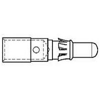
D SUB CONTACT, PIN, 18-16AWG, CRIMP

212013-1

Manufacturer Part Number
212013-1
Description
D SUB CONTACT, PIN, 18-16AWG, CRIMP
Manufacturer
TE Connectivity
Series
AMPLIMITE 109r
Datasheets

Specifications of 212013-1

Contact Plating
Gold
Contact Material
Copper Alloy
Wire Size (awg)
18-16
Contact Termination
Crimp
Contact Type
Power
Contact Size
8
Connector Type
Contact, Crimp
Rohs Compliant
Yes
Contact Gender
Pin
Product
Contacts
Shell Plating
Gold
Gender
Male
Mounting Style
Wire
Termination Style
Crimp
Features
Contact
Insulation
Not Insulated
Wire Gauge Range
18-16
Product Type
Contact
Product Series
109
Termination Method To Wire/cable
Crimp
High Current
No
Wire Range (mm [awg])
0.80-1.40² [18-16]
Retention Clip Material
Beryllium Copper
Contact Style
Power
Contact Base Material
Copper Alloy
Contact Plating, Mating Area, Material
Gold (50)
Density
Standard
Government/industry Qualification
No
Rohs/elv Compliance
RoHS compliant, ELV compliant
Lead Free Solder Processes
Not relevant for lead free process
Rohs/elv Compliance History
Always was RoHS compliant
Nasa Qualification
No
Applies To
Wire/Cable
Packaging Method
Loose Piece
Lead Free Status / Rohs Status
 Details
1.
1.1.
1.2.
2.
2.1.
2.2.
3.
3.1.
3.2.
©2011 Tyco Electronics Corporation,
a TE Connectivity Ltd. Company
All Rights Reserved
TE logo is a trademark.
SCOPE
Content
This specification covers perform ance, tests and quality requirem ents for AMPLIMITE* power pin and
socket contacts.
Qualification
W hen tests are perform ed on the subject product line, procedures specified in 109 Series Test
Specifications shall be used. All inspections shall be perform ed using the applicable inspection plan and
product drawing.
APPLICABLE DOCUM ENTS
The following docum ents form a part of this specification to the extent specified herein. Unless
otherwise specified, the latest edition of the docum ent applies. In the event of conflict between the
requirem ents of this specification and the product drawing, the product drawing shall take precedence.
In the event of conflict between the requirem ents of this specification and the referenced docum ents,
this specification shall take precedence.
TE Connectivity (TE) Docum ents
!
!
!
!
!
Military Specifications
!
!
REQUIREM ENTS
Design and Construction
Product shall be of design, construction and physical dim ensions specified on applicable product
drawing.
Materials
!
!
109-1: General Requirem ents for Test Specifications
109 Series: Test Specifications as indicated in Figure 1
114-10014: Application Specification
408-7516: Instruction Sheet
501-282: Qualification Test Report
MIL-W -16878/5: W ire, Electrical, Polytetrafluoroethylene (PTFE) Insulated, 200 C, 1000 Volts,
Extruded Insulated
MIL-W -22759: W ire, Electrical, Fluoropolym er Insulated, Copper or Copper Alloy
Pin: Brass, gold over nickel plating
Socket: Beryllium copper, gold over nickel plating
| Indicates change
*Trademark
Product
Specification
Connector, AMPLIMITE*, Power VIII
For latest revision, visit our website at www.te.com/documents.
For Regional Customer Service, visit our website at www.te.com
Other products, logos, and company names might be trademarks of their respective owners.
108-10045
11Mar11 Rev B
1 of 6
LOC B

Related parts for 212013-1

212013-1 Summary of contents

Page 1

... Pin: Brass, gold over nickel plating ! Socket: Beryllium copper, gold over nickel plating ©2011 Tyco Electronics Corporation, | Indicates change a TE Connectivity Ltd. Company *Trademark All Rights Reserved TE logo is a trademark. For latest revision, visit our website at www.te.com/documents. For Regional Customer Service, visit our website at www.te.com Other products, logos, and company names might be trademarks of their respective owners ...

Page 2

Ratings ! Current: See Figure 4 for applicable current carrying capability. Maxim um rated current that can be carried by this product is lim ited by its application, m axim um operating tem perature of housings, allowable tem perature ...

Page 3

Test Description Physical shock. Durability. Contact retention. Mating force. Unm ating force. Therm al shock. Hum idity-tem perature cycling. Tem perature life. Mixed flowing gas. Shall meet visual requirements, show no physical damage and shall meet requirements of NOTE additional ...

Page 4

Product Qualification and Requalification Test Sequence Test or Exam ination Exam ination of product Term ination resistance Insulation resistance Dielectric withstanding voltage Tem perature rise vs current Crim p tensile Vibration Physical shock Durability Contact retention Mating force Unm ...

Page 5

QUALITY ASSURANCE PROVISIONS 4.1. Qualification Testing A. Sam ple Selection Sam ples shall be prepared in accordance with applicable Instruction Sheets and shall be selected at random from current production. All test groups shall consist inim ...

Page 6

Percent Connector Loading Single Contact Am peres To determine acceptable current carrying capacity for percentage connector loading and wire gage NOTE indicated, use the Multiplication Factor (F) from the above chart and multiply it times the Base rated Current for ...

Related keywords