MCP4728-E/UN Microchip Technology, MCP4728-E/UN Datasheet - Page 49
MCP4728-E/UN
Manufacturer Part Number
MCP4728-E/UN
Description
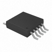
IC DAC 12BIT W/I2C 10-MSOP
Manufacturer
Microchip Technology
Specifications of MCP4728-E/UN
Number Of Converters
4
Settling Time
6µs
Package / Case
10-MSOP, Micro10™, 10-uMAX, 10-uSOP
Number Of Bits
12
Data Interface
I²C
Voltage Supply Source
Single Supply
Operating Temperature
-40°C ~ 125°C
Mounting Type
Surface Mount
Number Of Dac Outputs
4
Resolution
12 bit
Interface Type
I2C
Supply Voltage (max)
5.5 V
Supply Voltage (min)
2.7 V
Maximum Operating Temperature
+ 125 C
Mounting Style
SMD/SMT
Minimum Operating Temperature
- 40 C
Supply Current
110 mA
Voltage Reference
2.048 V
Lead Free Status / RoHS Status
Lead free / RoHS Compliant
For Use With
MCP4728EV - BOARD EVAL 12BIT 4CH DAC MCP4728
Power Dissipation (max)
-
Lead Free Status / Rohs Status
Lead free / RoHS Compliant
Available stocks
Company
Part Number
Manufacturer
Quantity
Price

Part Number:
MCP4728-E/UN
Manufacturer:
MICROCHIP/微芯
Quantity:
20 000


6.9
Offset error drift is the variation in offset error due to a
change in ambient temperature. The offset error drift is
typically expressed in ppm/
6.10
The Settling time is the time delay required for the DAC
output to settle to its new output value from the start of
code transition, within specified accuracy. In the
MCP4728 device, the settling time is a measure of the
time delay until the DAC output reaches its final value
within 0.5 LSB when the DAC code changes from 400h
to C00h.
6.11
Major-code transition glitch is the impulse energy
injected into the DAC analog output when the code in
the DAC register changes state. It is normally specified
as the area of the glitch in nV-Sec. and is measured
when the digital code is changed by 1 LSB at the major
carry transition (Example: 011...111 to 100...
000, or 100... 000 to 011... 111).
6.12
Digital feedthrough is a glitch that appears at the
analog output caused by coupling from the digital input
pins of the device. The area of the glitch is expressed
in nV-Sec, and is measured with a full scale change
(Example: all 0s to all 1s and vice versa) on the digital
input pins. The digital feedthrough is measured when
the DAC is not being written to the output register. This
condition can be created by writing the input register
with both the UDAC bit and the LDAC pin high.
© 2010 Microchip Technology Inc.
Offset Error Drift
Settling Time
Major-Code Transition Glitch
Digital Feedthrough
o
C.
6.13
Analog crosstalk is a glitch that appears at the output of
one DAC due to a change in the output of the other
DAC. The area of the glitch is expressed in nV-Sec,
and measured by loading one of the input registers with
a full scale code change (all 0s to all 1s and vice versa)
while keeping both the UDAC bit and the LDAC pin
high. Then bring down the LDAC pin to low and mea-
sure the output of the DAC whose digital code was not
changed.
6.14
DAC-to-DAC crosstalk is the glitch that appears at the
output of one DAC due to an input code change and
subsequent output change of the other DAC. This
includes both digital and analog crosstalks. The area of
the glitch is expressed in nV-Sec, and measured by
loading one of the input registers with a full scale code
change (all 0s to all 1s and vice versa) while keeping
UDAC bit or LDAC pin low.
6.15
PSRR indicates how the output of the DAC is affected
by changes in the supply voltage. PSRR is the ratio of
the change in V
output of the DAC. It is measured on one DAC that is
using an internal V
and expressed in dB or µV/V.
Analog Crosstalk
DAC-to-DAC Crosstalk
Power-Supply Rejection Ratio
(PSRR)
OUT
REF
to a change in V
while the V
MCP4728
DD
DS22187E-page 49
DD
is varied ±10%,
for full scale
Related parts for MCP4728-E/UN
Image
Part Number
Description
Manufacturer
Datasheet
Request
R

Part Number:
Description:
12-bit, Quad Digital-to-analog Converter With Eeprom Memory
Manufacturer:
Microchip Technology Inc.
Datasheet:
Part Number:
Description:
Manufacturer:
Microchip Technology Inc.
Datasheet:
Part Number:
Description:
Manufacturer:
Microchip Technology Inc.
Datasheet:
Part Number:
Description:
Manufacturer:
Microchip Technology Inc.
Datasheet:
Part Number:
Description:
Manufacturer:
Microchip Technology Inc.
Datasheet:
Part Number:
Description:
Manufacturer:
Microchip Technology Inc.
Datasheet:
Part Number:
Description:
Manufacturer:
Microchip Technology Inc.
Datasheet:
Part Number:
Description:
Manufacturer:
Microchip Technology Inc.
Datasheet:
Part Number:
Description:
Manufacturer:
Microchip Technology Inc.
Datasheet: