DS1858E-050+ Maxim Integrated Products, DS1858E-050+ Datasheet - Page 17

DS1858E-050+
Manufacturer Part Number
DS1858E-050+
Description
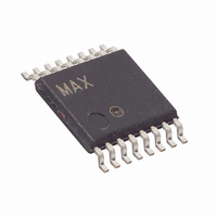
IC RES TEMP 50/50K 3MON 16-TSSOP
Manufacturer
Maxim Integrated Products
Datasheet
1.DS1858E-050.pdf
(22 pages)
Specifications of DS1858E-050+
Taps
256
Resistance (ohms)
50K
Number Of Circuits
2
Temperature Coefficient
50 ppm/°C Typical
Memory Type
Non-Volatile
Interface
I²C, 2-Wire Serial
Voltage - Supply
3 V ~ 5.5 V
Operating Temperature
-40°C ~ 95°C
Mounting Type
Surface Mount
Package / Case
16-TSSOP
Resistance In Ohms
50K
Lead Free Status / RoHS Status
Lead free / RoHS Compliant
Table 02h
Table 03h
Table 01h (continued)
LOCATION
MEMORY
LOCATION
LOCATION
8A to 8B
8D to 8F
MEMORY
MEMORY
80 to C7
80 to C7
F0 to FF
F0 to FF
(hex)
(hex)
(hex)
8C
5
4
3
2
1
0
EEPROM/
EEPROM
EEPROM
EEPROM
SRAM
EEPROM/
EEPROM/
EEPROM
EEPROM
EEPROM
EEPROM
—
—
—
—
—
—
SRAM
SRAM
R/W
R/W
—
—
—
—
—
—
—
—
R/W
R/W
R/W
R/W
R
R
DEFAULT
SETTING
(hex)
DEFAULT
DEFAULT
____________________________________________________________________
SETTING
SETTING
A2
00
—
0
0
0
0
0
0
(hex)
(hex)
FF
FF
FF
FF
Resistors with Three Monitors
Dual Temperature-Controlled
Device address
LOCATION
NAME OF
Reserved
Reserved
NAME OF LOCATION
NAME OF LOCATION
ADFIX
MPEN
ADEN
APEN
Resistor 0 Temp LUT
Resistor 1 Temp LUT
INV1
INV2
Reserved
Reserved
Controls if the device responds to one or two device
addresses (see the Memory Description section and
Table 5).
Controls the means by which Main and Auxiliary Device
addresses are set (see the Memory Description section
and Table 5).
Controls auxiliary write protect. See the Memory
Description section.
Controls main write protect. See the Memory Description
section.
Configures buffer 1 with OUT1 = MINT +
(INV1 [XOR] IN1).
Configures buffer 2 with OUT2 = INV2 [XOR] IN2.
Contains Main Device address if the bit ADFIX = 1. If
ADFIX = 0, then address A2h is used.
Look-up table for Resistor 0.
Look-up table for Resistor 1.
FUNCTION
—
FUNCTION
FUNCTION
—
17


