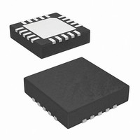
ISL22102IR20Z Intersil, ISL22102IR20Z Datasheet

ISL22102IR20Z
Specifications of ISL22102IR20Z
Available stocks
Related parts for ISL22102IR20Z
ISL22102IR20Z Summary of contents
Page 1
... CAUTION: These devices are sensitive to electrostatic discharge; follow proper IC Handling Procedures. 1-888-INTERSIL or 1-888-468-3774 XDCP is a trademark of Intersil Americas Inc. Copyright Intersil Americas Inc. 2008, 2010. All Rights Reserved All other trademarks mentioned are the property of their respective owners. ISL22102 FN6788.1 | Intersil (and design registered trademark of Intersil Americas Inc ...
Page 2
... PART MARKING ISL22102IV20Z* 22102 IVZ ISL22102IR20Z* 221 02IRZ *Add “-TK” suffix for tape and reel. Please refer to TB347 for details on reel specifications. NOTE: These Intersil Pb-free plastic packaged products employ special Pb-free material sets, molding compounds/die attach materials, and 100% matte tin plate plus anneal (e3 termination finish, which is RoHS compliant and compatible with both SnPb and Pb-free soldering operations) ...
Page 3
... EPAD* *Note: PCB thermal land for QFN/TDFN EPAD should be connected to GND plane or left floating. For more information refer to http://www.intersil.com/data/tb/TB389.pdf 3 ISL22102 GND 13 HPB 12 HPA Active low volume decrement input with internal pull-up. Active low mute input with internal pull-up. VCC Digital Power Supply. ...
Page 4
... Thermal Information Thermal Resistance (Typical) 20 Lead TSSOP (Note Lead QFN (Notes Maximum Junction Temperature (Plastic Package +150°C Pb-free Reflow Profile . . . . . . . . . . . . . . . . . . . . . . . . .see link below http://www.intersil.com/pbfree/Pb-FreeReflow.asp Recommended Operating Conditions Temperature Range (Industrial -40°C to 85°C Supply Voltage ( 2.7V to 5.5V CC Analog Supply Voltage (AV Power Rating of each DCP ...
Page 5
Analog Specifications Over the recommended operating conditions unless otherwise specified. SYMBOL PARAMETER TC Temperature Coefficient of End-to-end R (Note 7) Resistance DC ELECTRICAL SPECIFICATION AVCC Analog Power Supply VCC Digital Power Supply t AVCC and VCC Ramp Rate R I ...
Page 6
AC Timing Over recommended operating conditions (Continued) SYMBOL t FLAG Delay Time Interval Step Size, from D2:D0 = 001b to 111b. FLAG_LOW FLAG is Asserted LOW when Audio Input is Below Threshold. (See Table 1, page 7) t Zero Amplitude ...
Page 7
Pin Descriptions LEFT_IN, RIGHT_IN The LEFT_IN and RIGHT_IN pins of the ISL22102 are equivalent to the fixed terminals of a mechanical potentiometer. The stereo audio signal applied to these pins are referenced to VB and may have ±AVCC/2 maximum amplitude. ...
Page 8
V TH This terminal allows to set up the threshold level of audio input to be detected. When audio input to either Left or Right channel is below this threshold - the FLAG output is Low; when audio input is ...
Page 9
TABLE 3. WIPER TAP POSITION vs ATTENUATION (Continued) TAP POSITION Typical Application Diagram 1µF *FLAG LOW OUTPUT DELAY IS 240s 9 ISL22102 Once an UP MUTE ...
Page 10
Package Outline Drawing L20.4x4C 20 LEAD QUAD FLAT NO-LEAD PLASTIC PACKAGE Rev 0, 11/06 4.00 6 PIN 1 INDEX AREA 0.15 (4X) TOP VIEW ( 3. 8 TYP ) ( TYPICAL RECOMMENDED LAND PATTERN 10 ISL22102 16X ...
Page 11
... Accordingly, the reader is cautioned to verify that data sheets are current before placing orders. Information furnished by Intersil is believed to be accurate and reliable. However, no responsibility is assumed by Intersil or its subsidiaries for its use; nor for any infringements of patents or other rights of third parties which may result from its use ...


