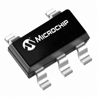
MCP4014T-202E/OT Microchip Technology, MCP4014T-202E/OT Datasheet - Page 43

MCP4014T-202E/OT
Manufacturer Part Number
MCP4014T-202E/OT
Description
IC DGTL POT 2.1K 1CH RHE SOT23-5
Manufacturer
Microchip Technology
Specifications of MCP4014T-202E/OT
Taps
64
Resistance (ohms)
2.1K
Number Of Circuits
1
Temperature Coefficient
150 ppm/°C Typical
Memory Type
Volatile
Interface
Up/Down
Voltage - Supply
1.8 V ~ 5.5 V
Operating Temperature
-40°C ~ 125°C
Mounting Type
Surface Mount
Package / Case
SOT-23-5, SC-74A, SOT-25
Resistance In Ohms
2.10K
End To End Resistance
2.1kohm
No. Of Steps
64
Resistance Tolerance
± 20%
Supply Voltage Range
2.7V To 5.5V
Control Interface
2 Wire, Serial
No. Of Pots
Single
Lead Free Status / RoHS Status
Lead free / RoHS Compliant
Other names
MCP4014T-202E/OTTR
8.0
Non-volatile digital potentiometers have a multitude of
practical uses in modern electronic circuits. The most
popular uses include precision calibration of set point
thresholds, sensor trimming, LCD bias trimming, audio
attenuation, adjustable power supplies, motor control
overcurrent trip setting, adjustable gain amplifiers and
offset trimming. The MCP4011/2/3/4 devices can be
used to replace the common mechanical trim pot in
applications where the operating and terminal voltages
are within CMOS process limitations (V
5.5V).
8.1
Applications that need accurate detection of an input
threshold event often need several sources of error
eliminated. Use of comparators and operational ampli-
fiers (op amps) with low offset and gain error can help
achieve the desired accuracy, but in many applications,
the input source variation is beyond the designer’s con-
trol. If the entire system can be calibrated after assem-
bly in a controlled environment (like factory test), these
sources of error are minimized, if not entirely
eliminated.
Figure 8-1 illustrates a common digital potentiometer
configuration. This configuration is often referred to as
a “windowed voltage divider”. Note that R
not necessary to create the voltage divider, but their
presence is useful when the desired threshold has
limited range. It is “windowed” because R
narrow the adjustable range of V
less than V
magnitude of each output step is reduced. This
effectively increases the trimming resolution for a fixed
digital potentiometer resolution. This technique may
allow a lower-cost digital potentiometer to be utilized
(64 steps instead of 256 steps).
The MCP4011’s and MCP4013’s low DNL performance
is critical to meeting calibration accuracy in production
without having to use a higher precision digital potenti-
ometer.
EQUATION 8-1:
© 2005 Microchip Technology Inc.
Where:
D
D = Digital Potentiometer Wiper Setting (0-63)
=
APPLICATIONS EXAMPLES
Set Point Threshold Trimming
⎛
⎝
DD
⎛
⎝
V
V
--------------
V
– V
TRIP
TRIP
DD
SS
R
⎞
⎠
R
=
WB
. If the output range is reduced, the
AB
V
CALCULATING THE
WIPER SETTING FROM
THE DESIRED V
DD
=
R
=
1
R
⎛
⎝
+
R
---------------------------------- -
R
AB
Nominal
R
1
R
AB
+
2
⎛
⎝
R
+
+
----- -
63
D
TRIP
AB
R
R
⎞
⎠
WB
2
+
R
to a value much
–
2
R
⎞
⎠
DD
2
1
1
TRIP
and R
⎞ 63
⎠
and R
= 2.7V to
2
2
can
are
FIGURE 8-1:
Potentiometer to Set a Precise Output Voltage.
8.1.1
If the application has to calibrate the threshold of a
diode, transistor or resistor, a variation range of 0.1V is
common. Often, the desired resolution of 2 mV or
better is adequate to accurately detect the presence of
a precise signal. A “windowed” voltage divider, utilizing
the MCP4011 or MCP4013, would be a potential
solution as shown in Figure 8-2.
FIGURE 8-2:
Calibration.
U/D
CS
MCP4011
R
U/D
R
CS
2
1
V
TRIMMING A THRESHOLD FOR AN
OPTICAL SENSOR
DD
MCP4011
B
A
MCP4011/2/3/4
W
V
0.1 μF
DD
Using the Digital
Set Point or Threshold
R
V
sense
DD
V
A
B
TRIP
R
R
1
2
W
Comparator
DS21978A-page 43
V
V
CC+
CC–
V
OUT
MCP6021


