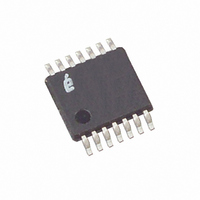
X9111TV14IZ-2.7 Intersil, X9111TV14IZ-2.7 Datasheet - Page 9

X9111TV14IZ-2.7
Manufacturer Part Number
X9111TV14IZ-2.7
Description
IC XDCP SGL 1024TAP 100K 14TSSOP
Manufacturer
Intersil
Series
XDCP™r
Datasheet
1.X9111TV14.pdf
(17 pages)
Specifications of X9111TV14IZ-2.7
Taps
1024
Resistance (ohms)
100K
Number Of Circuits
1
Temperature Coefficient
300 ppm/°C Typical
Memory Type
Non-Volatile
Interface
SPI, 3-Wire Serial
Voltage - Supply
2.7 V ~ 5.5 V
Operating Temperature
-40°C ~ 85°C
Mounting Type
Surface Mount
Package / Case
14-TSSOP
Resistance In Ohms
100K
Lead Free Status / RoHS Status
Lead free / RoHS Compliant
Available stocks
Company
Part Number
Manufacturer
Quantity
Price
Company:
Part Number:
X9111TV14IZ-2.7
Manufacturer:
TI
Quantity:
47
Absolute Maximum Ratings
Temperature under bias . . . . . . . . . . . . . . . . . . . . . .-65°C to +135°C
Storage temperature . . . . . . . . . . . . . . . . . . . . . . . .-65°C to +150°C
Voltage on SCK any address input
∆V = | (VH–VL) |. . . . . . . . . . . . . . . . . . . . . . . . . . . . . . . . . 0V to Vcc
Lead temperature (soldering, 10s). . . . . . . . . . . . . . . . . . . . . +300°C
I
CAUTION: Stresses above those listed in “Absolute Maximum Ratings” may cause permanent damage to the device. This is a stress only rating and operation of the
device at these or any other conditions above those indicated in the operational sections of this specification is not implied.
Analog Characteristics
NOTES:
W
1. Absolute linearity is utilized to determine actual wiper voltage versus expected voltage as determined by wiper position when used as a
2. Relative linearity is utilized to determine the actual change in voltage between two successive tap positions when used as a
3. MI = RTOT/1023 or (R
4. n = 0, 1, 2, …,1023; m =0, 1, 2, …, 1022.
5. ESD Rating on RH, RL, RW pins is 1.5kV (HBM, 1.0µA leakage maximum), ESD rating on all other pins is 2.0kV.
with respect to V
C
SYMBOL
(10s) . . . . . . . . . . . . . . . . . . . . . . . . . . . . . . . . . . . . . . . . . . ±6mA
R
V
H
potentiometer.
potentiometer. It is a measure of the error in step size.
TOTAL
/C
TERM
R
I
W
W
L
/C
W
End to End Resistance
End to End Resistance Tolerance
Power Rating
Wiper Current
Wiper Resistance
Voltage on any R
Noise
Resolution
Absolute Linearity (Note 1)
Relative Linearity (Note 2)
Temperature Coefficient of R
Ratiometric Temp. Coefficient
Potentiometer Capacitancies
SS
. . . . . . . . . . . . . . . . . . . . . . . . . . . -1V to +7V
H
– R
PARAMETER
Over recommended industrial operation conditions unless otherwise stated.
L
H
)/1023, single pot
9
or R
L
Pin
TOTAL
+25°C, each pot
Wiper Current = ±50µA,
V
Wiper Current = ±50µA,
V
V
Ref: 1V
R
n = 8 to 1006
R
R
1006
R
See Macro model
CC
CC
SS
w(n)(actual)
w(n)(actual)
w(m + 1)
w(m + 1)
= 0V
= 5V
= 3V
X9111
TEST CONDITIONS
-[R
-[R
-R
-R
w(m)
w(m)
w(n)(expected)
w(n)(expected)
+ MI], where m = 8 to
+ MI] (Note 4)
Recommended Operating Conditions
Temperature Range
Supply Voltage (V
Commercial . . . . . . . . . . . . . . . . . . . . . . . . . . . . . . . . 0°C to +70°C
Industrial . . . . . . . . . . . . . . . . . . . . . . . . . . . . . . . . .-40°C to +85°C
X9111 . . . . . . . . . . . . . . . . . . . . . . . . . . . . . . . . . . . . . . . . .5V ±10%
X9111-2.7 . . . . . . . . . . . . . . . . . . . . . . . . . . . . . . . . . . . 2.7V to 5.5V
, where
(Note 4)
CC
) Limits
MIN
V
SS
10/10/25
±300
TYP
-120
±1.5
±0.5
100
150
1.6
40
MAX
V
±2.0
±0.5
±1.0
±20
300
110
50
±3
±1
20
CC
September 15, 2006
MI (Note 3)
MI (Note 3)
MI (Note 3)
MI (Note 3)
ppm/°C
ppm/°C
UNITS
dBV
mW
mA
kΩ
pF
%
%
Ω
Ω
V
FN8159.4


