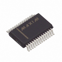
MAX1414CAI+ Maxim Integrated Products, MAX1414CAI+ Datasheet - Page 15

MAX1414CAI+
Manufacturer Part Number
MAX1414CAI+
Description
IC DAS 16BIT LP 28-SSOP
Manufacturer
Maxim Integrated Products
Type
Data Acquisition System (DAS)r
Datasheet
1.MAX1409CAP.pdf
(48 pages)
Specifications of MAX1414CAI+
Resolution (bits)
16 b
Sampling Rate (per Second)
60
Data Interface
Serial
Voltage Supply Source
Analog and Digital
Voltage - Supply
2.7 V ~ 3.6 V
Operating Temperature
0°C ~ 70°C
Mounting Type
Surface Mount
Package / Case
28-SSOP
Number Of Converters
1
Resolution
16 bit
Interface Type
Serial (4-Wire, SPI, QSPI, Microwire)
Supply Voltage (max)
3.6 V
Supply Voltage (min)
2.7 V
Maximum Power Dissipation
762 mW
Maximum Operating Temperature
+ 70 C
Mounting Style
SMD/SMT
Minimum Operating Temperature
0 C
Lead Free Status / RoHS Status
Lead free / RoHS Compliant
The MAX1407/MAX1408/MAX1409/MAX1414 are low-
power, general-purpose, multichannel DAS featuring a
multiplexed fully differential 16-bit ∑∆ analog-to-digital
converter (ADC), 10-bit force/sense digital-to-analog
converters (DAC), a real-time clock (RTC) with an
alarm, a bandgap voltage reference, a signal detect
comparator, two power-supply voltage monitors, wake-
up control circuitry, and a high-frequency phase-locked
loop (PLL) clock output all controlled by a 3-wire serial
interface. (See Table 1 for the MAX1407/MAX1408/
Table 1. MAX1407/MAX1408/MAX1409/MAX1414 Feature Sets
PART
MAX1407
MAX1414
MAX1408
MAX1409
MAX1407
MAX1414
20
21
22
23
24
25
26
27
28
—
AUXILIARY
MAX1408
ANALOG
INPUTS
Low-Power, 16-Bit Multichannel DAS with
ADC
20
21
22
23
24
25
26
27
28
—
Internal Reference,10-Bit DACs, and RTC
4
4
8
1
______________________________________________________________________________________
Detailed Information
MAX1409
FORCE/
SENSE
DAC
14
16
17
18
19
20
15
—
—
—
2
2
0
1
DIGITAL
OUTPUT
THREE-
STATE
DGND
DOUT
SCLK
DV
OUT2
DIN
PIN
Yes
Yes
Yes
INT
IN3
IN5
CS
No
DD
Active-Low Interrupt Output. INT goes low when the PLL output is ready,
when the signal-detect comparator is tripped, or when the alarm is triggered.
Serial Data Output. DOUT outputs serial data from the internal shift register
on SCLK’s falling edge. When CS is high, DOUT is three-stated.
Serial Data Input. Data on DIN is written to the input shift register and is
clocked in at SCLK’s rising edge when CS is low.
Serial Clock Input. Apply an external serial clock to transfer data to and from
the device. This serial clock can be continuous, with data transmitted in a
train of pulses, or intermittent while CS is low.
Active-Low Chip-Select Input. CS is used to select the active device in
systems with more than one device on the serial bus. Data will not be
clocked into DIN unless CS is low. When CS is high, DOUT is three-stated.
Digital Ground. Reference point for digital circuitry.
Digital Supply Voltage
Analog Input. Analog input to both the positive and negative mux.
Force/Sense DAC2 Output
Analog Input. Analog input to the positive mux only.
COMPARATOR
THRESHOLD
(mV)
50
0
0
0
MAX1409/MAX1414 feature sets and Figures 1, 2, 3 for
the Functional Diagrams). These DAS directly interface
to various sensor outputs and once configured provide
the stimulus, conditioning, and data conversion, as well
as microprocessor support. Figure 4 is a Typical
Application Circuit for the MAX1407/MAX1414.
The 16-bit ∑∆ ADC is capable of programmable contin-
uous conversion rates of 30Hz or 60Hz and gains of
1/3, 1, and 2V/V to suit applications with different power
and dynamic range constraints. The force/sense DACs
provide 10-bit linearity for precise sensor applications.
RTC
Yes
Yes
Yes
Yes
Pin Description (continued)
ADC DATA
READY
(DRDY)
FUNCTION
Yes
Yes
Yes
No
SHUTDOWN
EXTERNAL
CONTROL
POWER-
SUPPLY
Yes
Yes
Yes
No
DIFFERENTIAL
INPUT MUX
ADC
8
8
8
4
15


