927837-4 TE Connectivity, 927837-4 Datasheet - Page 5
927837-4
Manufacturer Part Number
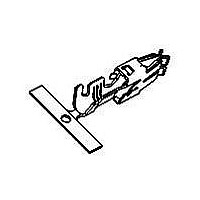
927837-4
Description
STD POWER TIMER
Manufacturer
TE Connectivity
Series
Standard Power-Timerr
Specifications of 927837-4
Product
Terminals
Gender
Female
Mounting Method
Wire
Mounting Style
Cable
Contact Plating
Pre-Silver
Product Type
Contact
Mating Area Interface Dimensions (mm [in])
4.75 x 0.81 [.187 x .032]
Wire/cable Type
Regular Wire
Insulation Support
With
Wire Range (mm [awg])
1.50-2.50² [15.5-13.5]
Single Wire Sealing System
No
Insulation Type
FLR (Thin Walled Cable)
Cantilever Spring Material
Stainless Steel
Contact Type
Socket
Contact Base Material
CuSn4
Contact Plating, Mating Area, Material
Pre-Silver
Rohs/elv Compliance
RoHS compliant, ELV compliant
Lead Free Solder Processes
Not relevant for lead free process
Rohs/elv Compliance History
Always was RoHS compliant
Accepts Wire Insulation Diameter, Range (mm [in])
2.11 – 3.10 [0.083 – 0.122]
Applies To
Wire/Cable
Packaging Method
Strip
Lead Free Status / Rohs Status
Details


66
Catalog 1773096
Revised 2-10
www.tycoelectronics.com
Strain Relief and Wire Dress
If required, wires can be bundled together and supported
with cable ties. Wires must not be stretched or confined in
any way that would restrict the floating action of the con-
nectors. Therefore, the wires must remain perpendicular to
the connector and avoid an excessively sharp bend
radius. The minimum recommended distance for the cable
tie, and the minimum bend radius of a wire bundle are
shown in the figure to the right.
PCB Fix Mounting
When mounting to a PC board, the connector standoffs must be seated on the board. Hold-downs are recommended to
provide stability during the soldering procedure. PCB-mount hole patterns are shown on the customer drawing specific
to your ELCON drawer connector.
Connector Engagement
To provide for proper mating of the connector when the power supply unit is fully engaged into the system, the gap
between the pin and socket (shown as dimension “A” in the sketch below) must be within the limit specified in the
customer drawing for your ELCON drawer connector. Failure to meet this requirement may compromise contact wipe.
Refer to the customer drawing for details. ELCON drawer connectors are polarized and will only mate in the correct
orientation (see sketch below).
Dimensions are in inches and
millimeters unless otherwise
specified. Values in brackets
are metric equivalents.
Power Connectors & Interconnection Systems
ELCON Drawer Connector Mounting
Flush PCB-Mount Drawer Connectors
.020 [0.51]
Dimensions are shown for
reference purposes only.
Specifications subject
to change.
Connector
PC Board (Ref)
Rib in Guide
Post Cavity
USA: 1-800-522-6752
Canada: 1-905-470-4425
Mexico: 01-800-733-8926
C. America: 52-55-1106-0803
(Continued)
Drawer Connectors with Cabled AC IN
.020 [0.51]
Guide Post
Notch in
South America: 55-11-2103-6000
Hong Kong: 852-2735-1628
Japan: 81-44-844-8013
UK: 44-(0)8002-67666
Standoffs
Wire
Related parts for 927837-4
Image
Part Number
Description
Manufacturer
Datasheet
Request
R

Part Number:
Description:
HC STD-TIMER KONT
Manufacturer:
TE Connectivity
Datasheet:
Part Number:
Description:
STD POWER TIMER
Manufacturer:
TE Connectivity
Datasheet:

Part Number:
Description:
High Speed / Modular Connectors 30P HEADER ASSY
Manufacturer:
TE Connectivity
Datasheet:

Part Number:
Description:
High Speed / Modular Connectors REC 6X005P R/A LT B-PLANE HS3
Manufacturer:
TE Connectivity
Datasheet:

Part Number:
Description:
High Speed / Modular Connectors 2MM HM RCPT 50P R/A AU
Manufacturer:
TE Connectivity
Datasheet:

Part Number:
Description:
High Speed / Modular Connectors 2MM HM RCPT 50P R/A AU
Manufacturer:
TE Connectivity
Datasheet:


Part Number:
Description:
Manufacturer:
TE Connectivity
Datasheet:


Part Number:
Description:
Manufacturer:
TE Connectivity
Datasheet:

Part Number:
Description:
Manufacturer:
TE Connectivity
Datasheet:

Part Number:
Description:
Manufacturer:
TE Connectivity
Datasheet: