AD7715AN-5 Analog Devices Inc, AD7715AN-5 Datasheet - Page 25
AD7715AN-5
Manufacturer Part Number
AD7715AN-5
Description
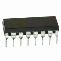
IC ADC 16BIT 5V 16-DIP
Manufacturer
Analog Devices Inc
Datasheet
1.AD7715ANZ-5.pdf
(40 pages)
Specifications of AD7715AN-5
Data Interface
DSP, MICROWIRE™, QSPI™, Serial, SPI™
Rohs Status
RoHS non-compliant
Number Of Bits
16
Sampling Rate (per Second)
500
Number Of Converters
1
Power Dissipation (max)
9.5mW
Voltage Supply Source
Analog and Digital
Operating Temperature
-40°C ~ 85°C
Mounting Type
Through Hole
Package / Case
16-DIP (0.300", 7.62mm)
Resolution (bits)
16bit
Sampling Rate
500SPS
Input Channel Type
Differential
Supply Voltage Range - Analog
4.75V To 5.25V
Supply Current
1.1mA
Digital Ic Case Style
DIP
For Use With
EVAL-AD7715-3EBZ - BOARD EVALUATION FOR AD7715
Lead Free Status / RoHS Status
Contains lead / RoHS non-compliant
Available stocks
Company
Part Number
Manufacturer
Quantity
Price
Company:

Part Number:
AD7715AN-5
Manufacturer:
AD
Quantity:
872
Company:
Part Number:
AD7715AN-5
Manufacturer:
AD
Quantity:
900
Company:
Part Number:
AD7715AN-5
Manufacturer:
AD
Quantity:
900
Part Number:
AD7715AN-5
Manufacturer:
ADI/亚德诺
Quantity:
20 000


If the part is used in unipolar mode with a required span of
0.8 × V
calibration can handle is from −1.05 × V
V
span of V
calibration can handle is from −1.05 × V
V
required to remove an offset of 0.2 × V
range which the system calibration can handle is 0.85 ×
V
If the part is used in bipolar mode with a required span of ±0.4 ×
V
can handle is from −0.65 × V
the part is used in bipolar mode with a required span of ±V
GAIN, then the offset range which the system calibration can
handle is from −0.05 × V
Similarly, if the part is used in bipolar mode and required to
remove an offset of ±0.2 × V
which the system calibration can handle is ±0.85 × V
REF
REF
REF
REF
/GAIN. If the part is used in unipolar mode with a required
/GAIN. Similarly, if the part is used in unipolar mode and
/GAIN.
/GAIN, then the offset range which the system calibration
REF
REF
/GAIN, then the offset range which the system
/GAIN, then the offset range which the system
REF
/GAIN to +0.05 × V
REF
REF
/GAIN, then the span range
/GAIN to +0.65 × V
REF
REF
REF
/GAIN, then the span
/GAIN to +0.25 ×
/GAIN to +0.05 ×
REF
/GAIN.
REF
REF
/GAIN. If
/GAIN.
REF
Rev. D | Page 25 of 40
/
Power-Up and Calibration
On power-up, the AD7715 performs an internal reset that sets
the contents of the internal registers to a known state. There are
default values loaded to all registers after a power-on or reset.
The default values contain nominal calibration coefficients for
the calibration registers. However, to ensure correct calibration
for the device a calibration routine should be performed after
power-up.
The power dissipation and temperature drift of the AD7715
are low, and no warm-up time is required before the initial
calibration is performed. However, if an external reference is
being used, this reference must have stabilized before calibration is
initiated. Similarly, if the clock source for the part is generated
from a crystal or resonator across the MCLK pins, the start-up
time for the oscillator circuit should elapse before a calibration
is initiated on the part (see the Clocking and Oscillator Circuit
section).
AD7715
Related parts for AD7715AN-5
Image
Part Number
Description
Manufacturer
Datasheet
Request
R

Part Number:
Description:
±1.7g Dual-Axis IMEMS Accelerometer Evaluation Board
Manufacturer:
Analog Devices Inc
Datasheet:

Part Number:
Description:
Inertial Sensor Evaluation System
Manufacturer:
Analog Devices Inc
Datasheet:
Part Number:
Description:
Manufacturer:
Analog Devices Inc
Datasheet:
Part Number:
Description:
Manufacturer:
Analog Devices Inc
Datasheet:
Part Number:
Description:
Manufacturer:
Analog Devices Inc
Datasheet:
Part Number:
Description:
Manufacturer:
Analog Devices Inc
Datasheet:
Part Number:
Description:
Manufacturer:
Analog Devices Inc
Datasheet:
Part Number:
Description:
Manufacturer:
Analog Devices Inc
Datasheet:
Part Number:
Description:
Manufacturer:
Analog Devices Inc
Datasheet:
Part Number:
Description:
Manufacturer:
Analog Devices Inc
Datasheet:
Part Number:
Description:
Manufacturer:
Analog Devices Inc
Datasheet:
Part Number:
Description:
Manufacturer:
Analog Devices Inc
Datasheet:
Part Number:
Description:
Manufacturer:
Analog Devices Inc
Datasheet: