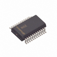
MAX1168BCEG+ Maxim Integrated Products, MAX1168BCEG+ Datasheet - Page 27

MAX1168BCEG+
Manufacturer Part Number
MAX1168BCEG+
Description
IC ADC 16BIT 200KSPS 24-QSOP
Manufacturer
Maxim Integrated Products
Datasheet
1.MAX1167BEEE.pdf
(30 pages)
Specifications of MAX1168BCEG+
Number Of Bits
16
Sampling Rate (per Second)
200k
Data Interface
MICROWIRE™, QSPI™, Serial, SPI™
Number Of Converters
1
Power Dissipation (max)
762mW
Voltage Supply Source
Analog and Digital
Operating Temperature
0°C ~ 70°C
Mounting Type
Surface Mount
Package / Case
24-QSOP
Lead Free Status / RoHS Status
Lead free / RoHS Compliant
Figure 24. Effective Bits vs. Frequency
The DSP mode of the MAX1168 only operates in exter-
nal clock mode. Figure 23 shows a typical DSP interface
connection to the MAX1168. Use the same oscillator as
the DSP to provide the clock signal for the MAX1168.
The DSP provides the falling edge at CS to wake the
MAX1168. The MAX1168 detects the state of DSPR on
the falling edge of CS (Figure 17). Logic low at DSPR
places the MAX1168 in DSP mode. After the MAX1168
enters DSP mode, CS can be left low. A frame sync
pulse from the DSP to DSPR initiates a conversion. The
MAX1168 sends a frame sync pulse from DSPX to the
DSP signaling that the MSB is available at DOUT. Send
another frame sync pulse from the DSP to DSPR to
begin the next conversion. The MAX1168 does not oper-
ate in scan mode when using DSP mode.
Integral nonlinearity (INL) is the deviation of the values
on an actual transfer function from a straight line. This
straight line can be either a best-straight-line fit or a line
drawn between the end points of the transfer function,
once offset and gain errors have been nullified. The
static linearity parameters for the MAX1167/MAX1168
are measured using the end-point method.
Differential nonlinearity (DNL) is the difference between
an actual step-width and the ideal value of ±1 LSB. A
DNL error specification of ±1 LSB guarantees no miss-
ing codes and a monotonic transfer function.
Multichannel, 16-Bit, 200ksps Analog-to-Digital
16
14
12
10
8
6
4
2
0
0.1
EFFECTIVE NUMBER OF BITS (ENOB)
______________________________________________________________________________________
FREQUENCY (kHz)
1
Differential Nonlinearity
Integral Nonlinearity
f
SAMPLE
10
= 200ksps
DSP Interface
Definitions
100
Aperture jitter (t
the time between samples. Aperture delay (t
time between the falling edge of the sampling clock
and the instant when the actual sample is taken.
For a waveform perfectly reconstructed from digital
samples, signal-to-noise ratio (SNR) is the ratio of the
full-scale analog input (RMS value) to the RMS quanti-
zation error (residual error). The ideal, theoretical mini-
mum analog-to-digital noise is caused by quantization
noise error only and results directly from the ADC’s res-
olution (N bits):
In reality, there are other noise sources besides quanti-
zation noise: thermal noise, reference noise, clock jitter,
etc. SNR is computed by taking the ratio of the RMS
signal to the RMS noise, which includes all spectral
components minus the fundamental, the first five har-
monics, and the DC offset.
Signal-to-noise plus distortion (SINAD) is the ratio of the
fundamental input frequency’s RMS amplitude to the
RMS equivalent of all the other ADC output signals:
Figure 25. Powering AV
AIN_
+5V
SINAD (dB) = 20
1μF
0.1μF
SNR = (6.02
AJ
Signal-to-Noise Plus Distortion
) is the sample-to-sample variation in
Distortion)
DD
10Ω
0.1μF
✕
and DV
log [Signal
DV
REF
AV
AIN_
✕
DD
DD
Signal-to-Noise Ratio
Converters
N + 1.76)dB
Aperture Definitions
DD
RMS
MAX1167
MAX1168
from a Single Supply
]
RMS
GND
DGND
AGND
AGND
SCLK
DOUT
/ (Noise +
CS
AD
DOUT
SCLK
) is the
CS
27


