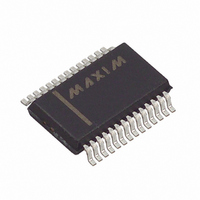
MAX1496EAI+ Maxim Integrated Products, MAX1496EAI+ Datasheet - Page 9

MAX1496EAI+
Manufacturer Part Number
MAX1496EAI+
Description
IC ADC 3.5DIGIT LED DRVR 28-SSOP
Manufacturer
Maxim Integrated Products
Datasheet
1.MAX1496EAI.pdf
(24 pages)
Specifications of MAX1496EAI+
Number Of Bits
3.5 Digit
Sampling Rate (per Second)
5
Number Of Converters
1
Voltage Supply Source
Analog and Digital
Operating Temperature
-40°C ~ 85°C
Mounting Type
Surface Mount
Package / Case
28-SSOP
Lead Free Status / RoHS Status
Lead free / RoHS Compliant
MAX1496
10
11
12
13
14
15
16
17
18
1
2
3
4
5
6
7
8
9
PIN
MAX1447/
MAX1498
31
32
10
11
12
13
14
15
16
17
—
1
2
3
4
5
8
9
_______________________________________________________________________________________
DPSET1
DPSET2
INTREF
RANGE
NAME
VNEG
HOLD
GLED
PEAK
REF+
AIN+
DIG0
DIG1
DIG2
REF-
GND
AIN-
ISET
V
DD
3.5- and 4.5-Digit, Single-Chip ADCs
-2.5V Charge-Pump Voltage Output. Connect a 0.1µF capacitor to GND.
Negative Reference Voltage Input. For internal-reference operation, connect REF- to GND.
For external-reference operation, bypass REF- to GND with a 0.1µF capacitor and set V
from -2.2V to +2.2V, provided V
Positive Reference Voltage Input. For internal-reference operation, connect a 4.7µF
capacitor from REF+ to GND. For external-reference operation, bypass REF+ to GND with a
0.1µF capacitor and set V
Positive Analog Input. Positive side of fully differential analog input. Bypass AIN+ to GND
with a 0.1µF or greater capacitor.
Negative Analog Input. Negative side of fully differential analog input. Bypass AIN- to GND
with a 0.1µF or greater capacitor.
Segment Current Controller. Connect to ground through a resistor to set the segment
current. See Table 5 for current selection.
Ground
Analog and Digital Circuit Supply Voltage. Connect V
Bypass V
Internal-Reference Logic Input. Connect to GND to select external-reference mode. Connect
to DV
reference mode.
Range Logic Input. RANGE controls the fully differential analog input range. Connect to
GND for the ±2V input range. Connect to DV
the ±200mV input range.
Decimal-Point Logic-Input 1. Controls the decimal point of the LED. See the Decimal-Point
Control section.
Decimal-Point Logic-Input 2. Controls the decimal point of the LED. See the Decimal-Point
Control section.
Peak Logic Input. Connect to DV
highest ADC value on the LED. Connect to GND to disable the peak function.
Hold Logic Input. Connect to DV
current ADC value on the LED. Connect to GND to update the LED at a rate of 2.5Hz and
disable the hold function. For the MAX1447, only placing the device into hold mode initiates
an offset mismatch calibration. Assert HOLD high for a minimum of 2s to ensure the
completion of offset mismatch calibration.
Digit 0 Driver
Digit 1 Driver
Ground for LED Display Digit Driver
Digit 2 Driver
DD
for the MAX1447/MAX1498 and V
DD
to GND with a 0.1µF capacitor and a 4.7µF capacitor.
REF+
from -2.2V to +2.2V, provided V
REF+
DD
DD
(MAX1447/MAX1498) or V
(MAX1447/MAX1498) or V
> V
REF-
FUNCTION
DD
DD
.
for the MAX1496 to select the internal-
with LED Drivers
(MAX1447/MAX1498) or V
DD
to a +2.7V to +5.25V power supply.
DD
DD
REF+
Pin Description
(MAX1496) to hold the
(MAX1496) to display the
> V
REF-
DD
.
(MAX1496) for
REF-
9


