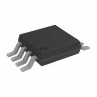
AD7921ARM-REEL7 Analog Devices Inc, AD7921ARM-REEL7 Datasheet - Page 17

AD7921ARM-REEL7
Manufacturer Part Number
AD7921ARM-REEL7
Description
IC ADC 12BIT DUAL LP 8-MSOP
Manufacturer
Analog Devices Inc
Datasheet
1.AD7921ARM-REEL7.pdf
(28 pages)
Specifications of AD7921ARM-REEL7
Number Of Bits
12
Sampling Rate (per Second)
250k
Data Interface
DSP, MICROWIRE™, QSPI™, Serial, SPI™
Number Of Converters
1
Power Dissipation (max)
20mW
Voltage Supply Source
Single Supply
Operating Temperature
-40°C ~ 85°C
Mounting Type
Surface Mount
Package / Case
8-TSSOP, 8-MSOP (0.118", 3.00mm Width)
Lead Free Status / RoHS Status
Contains lead / RoHS non-compliant
Other names
AD7921ARM-REEL7TR
Table 7 provides some typical performance data with various
op amps used as the input buffer, and a 50 kHz input tone under
the same setup conditions.
Table 7. AD7921 Performance for Various Input Buffers
Op Amp in the Input
Buffer
Single op amps
Dual op amps
When no amplifier is used to drive the analog input, the source
impedance should be limited to low values. The maximum
source impedance depends on the amount of total harmonic
distortion (THD) that can be tolerated. The THD increases as
the source impedance increases and performance degrades (see
Figure 16).
DIGITAL INPUTS
The digital inputs applied to the AD7911/AD7921 are not
limited by the maximum ratings that limit the analog input.
Instead, the digital inputs applied can go to 7 V and are not
restricted by the V
example, if the AD7911/AD7921 are operated with a V
then 5 V logic levels could be used on the digital inputs. How-
ever, it is important to note that the data output on DOUT still
has 3 V logic levels when V
SCLK, DIN, and CS not being restricted by the V
is that power supply sequencing issues are avoided. If CS , DIN,
or SCLK are applied before V
as there would be on the analog inputs, if a signal greater than
0.3 V were applied prior to V
AD8038
AD8510
AD8021
AD712
AD8022
DD
+ 0.3 V limit as on the analog input. For
DD
DD
DD
= 3 V. Another advantage of
AD7921 SNR Performance (dB)
50 kHz Input , V
−72.79
−72.35
−72.2
−72.68
−72.88
.
, then there is no risk of latch-up
DD
DD
= 3.6 V
+ 0.3 V limit
DD
of 3 V,
Rev. 0 | Page 17 of 28
DIN INPUT
The channel to be converted on in the next conversion is
selected by writing to the DIN pin. Data on the DIN pin is
loaded into the AD7911/AD7921 on the falling edge of SCLK.
The data is transferred into the part on the DIN pin at the same
time that the conversion result is read from the part.
Only the third bit of the DIN word is used; the rest are ignored
by the ADC. The third MSB is the channel identifier bit, which
identifies the channel to be converted on in the next conversion,
V
DOUT OUTPUT
The conversion result from the AD7911/AD7921 is provided on
this output as a serial data stream. The bits are clocked out on
the SCLK falling edge at the same time that the conversion is
taking place.
The serial data stream for the AD7921 consists of two leading
zeros followed by the bit that identifies the channel converted,
an invalid bit that matches up to the channel identifier bit, and
the 12-bit conversion result with MSB provided first.
For the AD7911, the serial data stream consists of two leading
zeros followed by the bit that identifies the channel converted,
an invalid bit that matches up to the channel identifier bit, and
the 10-bit conversion result with MSB provided first, followed
by two trailing zeros.
IN0
MSB
0
0
(CHN = 0) or V
MSB
X
0
0
CHN
CHN
X
Figure 25. AD7911/AD7921 DOUT Word
Figure 24. AD7911/AD7921 DIN Word
CHN
X
X
IN1
CONVERSION RESULT
(CHN = 1).
X
CONVERSION RESULT
DON'T CARE
AD7911/AD7921
0
LSB
0
LSB
AD7911
AD7921


