MCP3304-CI/SL Microchip Technology, MCP3304-CI/SL Datasheet - Page 28
MCP3304-CI/SL
Manufacturer Part Number
MCP3304-CI/SL
Description
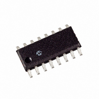
IC ADC 13BIT 2.7V 4CH SPI 16SOIC
Manufacturer
Microchip Technology
Specifications of MCP3304-CI/SL
Package / Case
16-SOIC (0.154", 3.90mm Width)
Number Of Bits
13
Sampling Rate (per Second)
100k
Data Interface
Serial, SPI™
Number Of Converters
1
Voltage Supply Source
Single Supply
Operating Temperature
-40°C ~ 85°C
Mounting Type
Surface Mount
Architecture
SAR
Conversion Rate
100 KSPs
Resolution
12 bit
Input Type
Voltage
Snr
80.02 dB
Maximum Operating Temperature
+ 85 C
Mounting Style
SMD/SMT
Minimum Operating Temperature
- 40 C
Lead Free Status / RoHS Status
Lead free / RoHS Compliant
Lead Free Status / RoHS Status
Lead free / RoHS Compliant, Lead free / RoHS Compliant
Other names
MCP3304CI/SL
Available stocks
Company
Part Number
Manufacturer
Quantity
Price
Company:

Part Number:
MCP3304-CI/SL
Manufacturer:
MICROCHIP
Quantity:
12 000
Part Number:
MCP3304-CI/SL
Manufacturer:
MICROCHIP/微芯
Quantity:
20 000


MCP3302/04
6.3
With most microcontroller SPI ports, it is required to
send groups of eight bits. It is also required that the
microcontroller SPI port be configured to clock out data
on the falling edge of clock and latch data in on the
rising
MCP3302 and MCP3304 devices may not need
multiples of eight clocks, it will be necessary to provide
more clocks than are required. This is usually done by
sending ‘leading zeros’ before the start bit. For
example,
MCP3302/04 devices can be interfaced to a MCU with
a hardware SPI port.
shown in SPI Mode 0,0, which requires that the SCLK
from the MCU idles in the ‘low’ state, while
shows the similar case of SPI Mode 1,1, where the
clock idles in the ‘high’ state.
FIGURE 6-4:
(Mode 0,0: SCLK idles low).
DS21697E-page 28
MCU Transmitted Data
(Aligned with falling
edge of clock)
MCU Received Data
(Aligned with rising
edge of clock)
? = Unknown Bits
X = Don’t Care Bits
SCLK
D
OUT
D
CS
IN
edge.
Using the MCP3302/04 with
Microcontroller (MCU) SPI Ports
Figure 6-4
MCU latches data from A/D Converter
on rising edges of SCLK
Because
1
?
Data stored into MCU receive
register after transmission of first 8
bits
0
2
Figure 6-4
and
SPI Communication with the MCP3302/04 using 8-bit segments
?
0
3
?
communication
Figure 6-5
0
4
HI-Z
?
Start
0
5
Data is clocked out of
A/D Converter on falling edges
depicts the operation
?
Start
Bit
SGL/
DIFF
1
6
?
SGL/
DIFF
D2
show how the
7
?
D2
D1
8
Figure 6-5
?
with
D1
D0
9
the
?
Data stored into MCU receive
register after transmission of
second 8 bits
DO
10
?
NULL
BIT
X
(Null)
11
0
SB
X
12
SB
As shown in
A/D Converter contains 6 leading zeros before the start
bit. Arranging the leading zeros this way produces the
13 data bits to fall in positions easily manipulated by the
MCU. The sign bit is clocked out of the A/D Converter
on the falling edge of clock number 11, followed by the
remaining data bits (MSB first). After the second eight
clocks have been sent to the device, the MCU receive
buffer will contain 2 unknown bits (the output is at high-
impedance for the first two clocks), the null bit, the sign
bit, and the 4 highest order bits of the conversion. After
the third byte has been sent to the device, the receive
register will contain the lowest order eight bits of the
conversion
converted data can be obtained by using this method.
Figure 6-5
which requires that the clock idles in the high state. As
with mode 0,0, the A/D Converter outputs data on the
falling edge of the clock and the MCU latches data from
the A/D Converter in on the rising edge of the clock.
B11 B10 B9
X
13
B11 B10 B9
X
14
X
15
shows the same situation in SPI Mode 1,1,
X
B8
16
Figure
B8
results. Easier manipulation
X
B7
Don’t Care
17
6-4, the first byte transmitted to the
B7
Data stored into MCU receive
register after transmission of last
8 bits
X
B6
18
B6
© 2008 Microchip Technology Inc.
X
B5
19
B5
X
B4
20
B4
X
B3
21
B3
X
B2
22
B2
X
B1
23
B1
X
B0
24
B0
of the
X
Related parts for MCP3304-CI/SL
Image
Part Number
Description
Manufacturer
Datasheet
Request
R

Part Number:
Description:
IC ADC 13BIT 2.7V 4CH SPI 16-DIP
Manufacturer:
Microchip Technology
Datasheet:
Part Number:
Description:
IC ADC 13BIT 2.7V 4CH SPI 16DIP
Manufacturer:
Microchip Technology
Datasheet:

Part Number:
Description:
ADC Single SAR 100KSPS 12-Bit+Sign Serial 16-Pin SOIC N Tube
Manufacturer:
Microchip Technology
Datasheet:
Part Number:
Description:
13-Bit Differential Input, Low Power A/D Converter with SPI Serial Interface
Manufacturer:
Microchip Technology
Datasheet:

Part Number:
Description:
Manufacturer:
Microchip Technology Inc.
Datasheet:
Part Number:
Description:
Manufacturer:
Microchip Technology Inc.
Datasheet:
Part Number:
Description:
Manufacturer:
Microchip Technology Inc.
Datasheet:
Part Number:
Description:
Manufacturer:
Microchip Technology Inc.
Datasheet:
Part Number:
Description:
Manufacturer:
Microchip Technology Inc.
Datasheet:
Part Number:
Description:
Manufacturer:
Microchip Technology Inc.
Datasheet:
Part Number:
Description:
Manufacturer:
Microchip Technology Inc.
Datasheet: