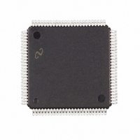
LM9832CCVJD National Semiconductor, LM9832CCVJD Datasheet - Page 12

LM9832CCVJD
Manufacturer Part Number
LM9832CCVJD
Description
IC SCANNER CLR USB IMAGE 100TQFP
Manufacturer
National Semiconductor
Datasheet
1.LM9832CCVJD.pdf
(42 pages)
Specifications of LM9832CCVJD
Number Of Bits
14
Number Of Channels
3
Voltage - Supply, Analog
5V
Voltage - Supply, Digital
5V
Package / Case
100-TQFP, 100-VQFP
Lead Free Status / RoHS Status
Contains lead / RoHS non-compliant
Power (watts)
-
Other names
*LM9832CCVJD
Available stocks
Company
Part Number
Manufacturer
Quantity
Price
Company:
Part Number:
LM9832CCVJD
Manufacturer:
Texas Instruments
Quantity:
10 000
Register Listing
Address
HORIZONTAL RESOLUTION AND DATAMODE SETTINGS
TURBO AND PREVIEW MODE SETTINGS
SENSOR CONFIGURATION
09
0A
0B
Horizontal DPI Divider
This register determines the horizontal
resolution of the scan.
Scan resolution = Optical resolution divided
by the Horizontal_DPI_Divider.
Pixel Packing
This register determines how many bits in
each byte of data are transmitted to the host
when DataMode = 0
DataMode
When DataMode = 0, the pixel data is fully
processed, going through the Offset,
Shading, Horizontal DPI Adjust, Gamma,
and Pixel Packing blocks.
When DataMode = 1, 14 bit data is extracted
following the Shading Multiplier stage.
Gamma and any other post processing must
be done by the host.
Analog Bias Current (Percent of Nominal)
The recommended setting is 80% for best
performance. Lower settings will reduce
power consumption further but may degrade
ADC INL and DNL performance.
Turbo/Preview Mode Select
Turbo/Preview Mode Speed
Input Signal Polarity
CDS On/Off
Standard/Even-Odd Sensor
CIS TR1 Timing Mode
Fake Optical Black Pixels
(for Dyna-type CIS sensors)
(Continued)
Function
D
7
0 0
0 1
1 0
1 1
D
6
D
0
1
0
1
5
D
0 0
0 1
1 0
1 1
0 0
0 1
1 0
1 1
4
12
D
3
0 0
0 1
1 0
1 1
D
0 0 0 ÷1
0 0 1 ÷1.5
0 1 0 ÷2
0 1 1 ÷3
1 0 0 ÷4
1 0 1 ÷6
1 1 0 ÷8
1 1 1 ÷12
0
1
2
D
0 0
0 1
1 0
1 1
0
1
1
D
0
0 Negative (Most CCD Sensors and Toshiba CIS)
1 Positive (Most CIS Sensors)
1 bit/pixel (1 bit grayscale/3 bit color)
2 bits/pixel (2 bit grayscale/6 bit color)
4 bits/pixel (4 bit grayscale/12 bit color)
8 bits/pixel (8 bit grayscale/24 bit color)
1, 2, 4, or 8 bit image data,
as determined by the Pixel Size setting.
14 bit image data - sent in 2 bytes, MSB first:
First Byte: 13 12 11 10 09 08 07 06
Second Byte: 05 04 03 02 01 00 XX XX
(XX: bits set to 0)
100% (analog supply current = ~81mA)
80% (analog supply current = ~65mA)
70% (analog supply current = ~57mA)
50% (analog supply current = ~41mA)
CDS Off
CDS On
Standard (1 pixels per Ø period)
Even/Odd (2 pixels per Ø period)
Off - use standard CCD Timing
CIS TR1 Timing Mode 1:
TR1 pulse = exactly one Ø clock,
starting at rising edge of Ø1
CIS TR1 Timing Mode 2:
TR1 pulse = exactly one Ø clock,
TR1 centered around Ø1 high.
N/A
Off: Normal operation
On: RS pulse held high for entire Optical Black period
x3 (3 Channel Pixel Rate Mode Only)
x4 (3 Channel Pixel Rate Mode Only)
x6 (3 Channel Pixel Rate Mode Only)
Preview Mode (for CCD Sensors)
Turbo Mode (for CIS Sensors)
Normal Operation
Value
N/A
x2
www.national.com


