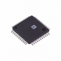
AD73360ASU Analog Devices Inc, AD73360ASU Datasheet

AD73360ASU
Manufacturer Part Number
AD73360ASU
Description
IC ANALOG FRONT END 6CH 44-TQFP
Manufacturer
Analog Devices Inc
Specifications of AD73360ASU
Number Of Channels
6
Rohs Status
RoHS non-compliant
Number Of Bits
16
Power (watts)
80mW
Voltage - Supply, Analog
3V
Voltage - Supply, Digital
3V
Package / Case
44-TQFP, 44-VQFP
Analog Front End Type
General Purpose
Analog Front End Category
General Purpose
Interface Type
Serial (6-Wire)
Sample Rate
64KSPS
Input Voltage Range
1.64375V
Operating Supply Voltage (min)
4.5V
Operating Supply Voltage (typ)
5V
Operating Supply Voltage (max)
5.5V
Resolution
16b
Number Of Adc's
6
Power Supply Type
Analog/Digital
Operating Temp Range
-40C to 85C
Operating Temperature Classification
Industrial
Mounting
Surface Mount
Pin Count
44
Package Type
TQFP
For Use With
EVAL-AD73360LEB - BOARD EVAL FOR AD73360L
Lead Free Status / RoHS Status
Not Compliant
Available stocks
Company
Part Number
Manufacturer
Quantity
Price
Company:
Part Number:
AD73360ASU
Manufacturer:
ADI
Quantity:
218
Part Number:
AD73360ASU
Manufacturer:
ADI/亚德诺
Quantity:
20 000
Company:
Part Number:
AD73360ASUZ
Manufacturer:
ADI
Quantity:
219
Company:
Part Number:
AD73360ASUZ
Manufacturer:
Analog Devices Inc
Quantity:
10 000
Company:
Part Number:
AD73360ASUZ-REEL
Manufacturer:
Analog Devices Inc
Quantity:
10 000
A. This document details the limitations of the cascading option of the AD73360 due to a bug in the current silicon.
B. Analog Devices Inc. is committed, through future silicon revisions to continuously improve silicon functionality.
Analog Devices Inc. will use its best endeavors to ensure that these future silicon revisions remain compatible with your
present software/systems implementing the recommended work-arounds outlined in this document.
Background
The AD73360 has the option of being cascaded allowing additional analog input channels to be easily be added as re-
quired. Due to a bug in the present silicon there are limitations on how many devices can be cascaded together and is
also dependent on the sample rate and serial clock rate used.
Issue Description
When a number of AD73360s are cascaded together they each output ADC channel data in a time-division multiplexed
(TDM) format. For a cascade of N devices with all channels enabled the output sequence read by a DSP or Micro-con-
troller would be
Device N – Channel 1, Device N-1 - Channel 1… Device 1 - Channel 1,
Device N - Channel 2, Device N-1 – Channel 2 … Device 1 – Channel 2…,
… ,
Device N – Channel 6, Device N-1 – Channel6 …, Device 1 – Channel 6
As each device is programmed with the number of devices in the cascade it should therefore allow sufficient SCLKs for
all other devices to transmit the ADC result of one channel before starting to transmit the next. For example in a cascade
of two devices, Device 1 will transmit its Channel 1 result to Device 2 in 16 SCLK cycles. At the same time Device 2 is
transmitting its Channel 1 result to the DSP or Microcontroller. Device 1 will then allow 16 SCLKs, when it does not
transmit anything, allowing Device 2 to transmit the Channel 1 data from Device 1 to the DSP. An additional SCLK
cycle is added to allow the next channels data to begin being transmitted on the falling edge of the SDOFS pulse. Figure
1 shows the timing for a two device cascade.
Rev.A 6-2000
Information furnished by Analog Devices is believed to be accurate and
reliable. However, no responsibility is assumed by Analog Devices for its
use, nor for any infringements of patents or other rights of third parties
which may result from its use. No license is granted by implication or
otherwise under any patent or patent rights of Analog Devices.
For cascades of more than two devices the AD73360 will leave too many SCLKs between transmitting channel
information. This increases the time it takes to transmit the ADC data and since a DSP or microcontroller must
read data from all the ADCs in the cascade in one sample period the number of devices which can be cascaded
will be limited. Figure 2 shows the effect the additional SCLKs have on a cascade of three devices.
1
2
3
4 5
DE V ICE 2 - CHA NNE L 1
6 7
8 9
10 11 12 13 14 15 16 1
Figure 1. Cascade Timing for a Two-Device Cascade
2
3
4 5
DE V ICE 1 - CHA NNE L 1
6 7
8 9
One Technology Way, P .O. Box 9106, Norwood, MA 02062-9106, U.S.A.
Tel: 781/329-4700
Fax: 781/326-8703
10 11 12 13 14 15 16 17
1
DE V ICE 2 - CHA NNE L 2
World Wide Web Site: http://www.analog.com
2
3
Errata Document
4 5
6 7
AD73360 Rev. 1
8
Analog Devices, Inc., 2000
Related parts for AD73360ASU
AD73360ASU Summary of contents
Page 1
... A. This document details the limitations of the cascading option of the AD73360 due to a bug in the current silicon. B. Analog Devices Inc. is committed, through future silicon revisions to continuously improve silicon functionality. Analog Devices Inc. will use its best endeavors to ensure that these future silicon revisions remain compatible with your present software/systems implementing the recommended work-arounds outlined in this document. ...
Page 2
ERRATA DOCUMENT vice ...


