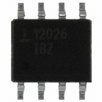
ISL12026IBZ Intersil, ISL12026IBZ Datasheet - Page 9

ISL12026IBZ
Manufacturer Part Number
ISL12026IBZ
Description
IC RTC/CALENDAR EEPROM 8-SOIC
Manufacturer
Intersil
Type
Clock/Calendar/EEPROMr
Specifications of ISL12026IBZ
Memory Size
4K (512 x 8)
Time Format
HH:MM:SS (12/24 hr)
Date Format
YY-MM-DD-dd
Interface
I²C, 2-Wire Serial
Voltage - Supply
2.7 V ~ 5.5 V
Operating Temperature
-40°C ~ 85°C
Mounting Type
Surface Mount
Package / Case
8-SOIC (3.9mm Width)
Clock Format
HH
Clock Ic Type
RTC
Interface Type
I2C, Serial
Memory Configuration
512 X 8
Supply Voltage Range
2.7V To 5.5V
Digital Ic Case Style
SOIC
Rohs Compliant
Yes
Lead Free Status / RoHS Status
Lead free / RoHS Compliant
Available stocks
Company
Part Number
Manufacturer
Quantity
Price
Company:
Part Number:
ISL12026IBZ
Manufacturer:
INTELSEL
Quantity:
60
Part Number:
ISL12026IBZ
Manufacturer:
INTERSIL
Quantity:
20 000
Part Number:
ISL12026IBZ-T
Manufacturer:
INTERSIL
Quantity:
20 000
24 Hour Time
If the MIL bit of the HR register is 1, the RTC uses a 24-hour
format. If the MIL bit is 0, the RTC uses a 12-hour format and
H21 bit functions as an AM/PM indicator with a ‘1’
representing PM. The clock defaults to standard time with
H21 = 0.
Leap Years
Leap years add the day February 29 and are defined as
those years that are divisible by 4.
Status Register (SR)
The Status Register is located in the CCR memory map at
address 003Fh. This is a volatile register only and is used to
control the WEL and RWEL write enable latches, read power
status and two alarm bits. This register is separate from both
the array and the Clock/Control Registers (CCR).
BAT: Battery Supply - Volatile
This bit set to “1” indicates that the device is operating from
V
hardware (ISL12026 internally). Once the device begins
operating from V
AL1, AL0: Alarm Bits - Volatile
These bits announce if either alarm 0 or alarm 1 match the
real time clock. If there is a match, the respective bit is set to
‘1’. The falling edge of the last data bit in a SR Read
operation resets the flags. Note: Only the AL bits that are set
when an SR read starts will be reset. An alarm bit that is set
by an alarm occurring during an SR read operation will
remain set after the read operation is complete.
OSCF: Oscillator Fail Indicator
This bit is set to “1” if the oscillator is not operating. The bit is
set to “0” only if the oscillator is functioning. This bit is read
only, and is set/reset by hardware.
Default
ADDR
003Fh
BAT
, not V
BAT
7
0
DD
TABLE 1. STATUS REGISTER (SR)
. It is a read-only bit and is set/reset by
AL1
DD
6
0
, the device sets this bit to “0”.
AL0 OSCF
5
0
4
0
9
3
0
0
RWEL WEL
2
0
1
0
RTCF
0
1
ISL12026
RWEL: Register Write Enable Latch - Volatile
This bit is a volatile latch that powers up in the LOW
(disabled) state. The RWEL bit must be set to “1” prior to any
writes to the Clock/Control Registers. Writes to RWEL bit do
not cause a non-volatile write cycle, so the device is ready
for the next operation immediately after the stop condition. A
write to the CCR requires both the RWEL and WEL bits to be
set in a specific sequence.
WEL: Write Enable Latch - Volatile
The WEL bit controls the access to the CCR during a write
operation. This bit is a volatile latch that powers up in the
LOW (disabled) state. While the WEL bit is LOW, writes to
the CCR address will be ignored, although acknowledgment
is still issued. The WEL bit is set by writing a “1” to the WEL
bit and zeroes to the other bits of the Status Register. Once
set, WEL remains set until either reset to 0 (by writing a “0”
to the WEL bit and zeroes to the other bits of the Status
Register) or until the part powers up again. Writes to WEL bit
do not cause a non-volatile write cycle, so the device is
ready for the next operation immediately after the stop
condition.
RTCF: Real Time Clock Fail Bit - Volatile
This bit is set to a “1” after a total power failure. This is a read
only bit that is set by hardware (ISL12026 internally) when
the device powers up after having lost all power to the device
(both V
whether V
the supplies does not set the RTCF bit to “1”. On power up
after a total power failure, all registers are set to their default
states and the clock will not increment until at least one byte
is written to the clock register. The first valid write to the RTC
section after a complete power failure resets the RTCF bit to
“0” (writing one byte is sufficient).
Unused Bits
Bit 3 in the SR is not used, but must be zero. The Data Byte
output during a SR read will contain a zero in this bit
location.
DD
DD
and V
or V
BAT
BAT
go to 0V). The bit is set regardless of
is applied first. The loss of only one of
October 23, 2006
FN8231.5


