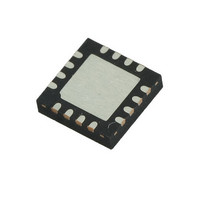
M41T83SQA6F STMicroelectronics, M41T83SQA6F Datasheet - Page 42

M41T83SQA6F
Manufacturer Part Number
M41T83SQA6F
Description
IC RTC SERIAL W/BATT SW 16QFN
Manufacturer
STMicroelectronics
Type
Clock/Calendar/Alarmr
Datasheet
1.M41T82SM6F.pdf
(61 pages)
Specifications of M41T83SQA6F
Memory Size
32B
Time Format
HH:MM:SS:hh (24 hr)
Date Format
YY-MM-DD-dd
Interface
I²C, 2-Wire Serial
Voltage - Supply
3 V ~ 5.5 V
Operating Temperature
-40°C ~ 85°C
Mounting Type
Surface Mount
Package / Case
16-QFN
Clock Format
12Hr / 24Hr
Clock Ic Type
RTC
Interface Type
I2C, Serial
Supply Voltage Range
3V To 5.5V
Digital Ic Case Style
QFN
No. Of Pins
16
Rohs Compliant
Yes
For Use With
497-10833 - DAUGHTER-CARD M41T83SQA6E QFN16
Lead Free Status / RoHS Status
Lead free / RoHS Compliant
Other names
497-6887-2
M41T83SQA6F
M41T83SQA6F
Available stocks
Company
Part Number
Manufacturer
Quantity
Price
Company:
Part Number:
M41T83SQA6F
Manufacturer:
STMicroelectronics
Quantity:
1 840
Company:
Part Number:
M41T83SQA6F
Manufacturer:
Maxim
Quantity:
20
Clock operation
3.14.1
Table 15.
1. OUT is bit 7 of register 08h (digital calibration).
2. FT is bit 6 of register 08h (digital calibration).
3. A1IE is bit 7 of register 0Ah (alarm 1, month).
4. OFIE is bit 7 of register 09h (watchdog).
5. TIE is bit 5 of register 11h (timer control).
6. The watchdog is controlled by register 09h (watchdog).
42/61
OUT
0
0
1
1
x
(1)
The timer, oscillator fail detect circuit, alarm 1, and watchdog are ORed together as the
primary interrupt sources. The frequency test signal, FT, is used to enable a 512 Hz output
on the IRQ1/FT/OUT pin for calibrating the RTC. When not used as an interrupt or
frequency test output, the pin can be used as a discrete logic output controlled by the OUT
bit. The ABE bit is used to enable interrupts during backup mode.
Operating on V
watchdog are disabled, and the only interrupt sources are alarm 1 and the oscillator fail
detect circuit.
Active mode operation on V
On V
Priority for IRQ1/FT/OUT pin when operating on V
When OUT is 0 and FT is 0, the pin will be 0 regardless of whether any interrupts are
enabled.
When FT is a 1, the 512 Hz signal will be output if OUT is 0 or if no interrupts are enabled.
The interrupt sources control the pin when OUT is 1 and one or more of the interrupts are
enabled.
If OUT is 1, FT is 0 and no interrupts are enabled, then the pin will be 1.
FT
0
1
1
0
x
CC
(2)
, the operation of the output circuit is as shown in
+ watchdog
+ OFIE
running
+ TIE
A1IE
CC
, all four interrupt sources are available. During backup, the timer and
0
1
0
x
x
(3)
(5)
(4)
(6)
512 Hz
Doc ID 12578 Rev 12
IRQ
Pin
0
1
CC
When OUT is 0 and FT is not enabled, OUT dominates
and none of the interrupt sources have any effect.
When FT = 1 and OUT = 1 and no interrupts are enabled,
the output will be the 512 Hz frequency test (FT) signal.
When one or more interrupts are enabled, and OUT is a 1,
the pin stays high until one of the interrupts is asserted.
When OUT is 1, FT is 0 and no interrupts are enabled, the
pin is high.
CC
Table
Comment
15.
M41T82-M41T83


