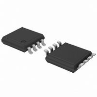
PCF8563TS/4,118 NXP Semiconductors, PCF8563TS/4,118 Datasheet - Page 16

PCF8563TS/4,118
Manufacturer Part Number
PCF8563TS/4,118
Description
IC REAL TIME CLK/CALENDAR 8TSSOP
Manufacturer
NXP Semiconductors
Type
Clock/Calendarr
Datasheet
1.PCF8563TF4118.pdf
(45 pages)
Specifications of PCF8563TS/4,118
Package / Case
8-TSSOP
Time Format
HH:MM:SS (24 hr)
Date Format
YY-MM-DD-dd
Interface
I²C, 2-Wire Serial
Voltage - Supply
1.8 V ~ 5.5 V
Operating Temperature
-40°C ~ 85°C
Mounting Type
Surface Mount
Function
Clock/Calendar/Alarm/Timer Interrupt
Supply Voltage (max)
5.5 V
Supply Voltage (min)
1.8 V
Maximum Operating Temperature
+ 85 C
Minimum Operating Temperature
- 40 C
Mounting Style
SMD/SMT
Rtc Bus Interface
Serial (2-Wire, I2C)
Lead Free Status / RoHS Status
Lead free / RoHS Compliant
For Use With
568-3615 - DEMO BOARD I2C
Memory Size
-
Lead Free Status / Rohs Status
Lead free / RoHS Compliant
Other names
568-4517-2
935279522118
PCF8563TS-T
PCF8563TS-T
935279522118
PCF8563TS-T
PCF8563TS-T
Available stocks
Company
Part Number
Manufacturer
Quantity
Price
Part Number:
PCF8563TS/4,118
Manufacturer:
NXP/恩智浦
Quantity:
20 000
NXP Semiconductors
PCF8563
Product data sheet
8.8.1 Register Timer_control
8.8 Timer function
Table 22.
[1]
The 8-bit countdown timer at address 0Fh is controlled by the Timer_control register at
address 0Eh. The Timer_control register determines one of 4 source clock frequencies for
the timer (4096 Hz, 64 Hz, 1 Hz, or
counts down from a software-loaded 8-bit binary value. At the end of every countdown,
the timer sets the timer flag TF. The TF may only be cleared by using the interface. The
asserted TF can be used to generate an interrupt on pin INT. The interrupt may be
generated as a pulsed signal every countdown period or as a permanently active signal
which follows the state of TF. Bit TI_TP is used to control this mode selection. When
reading the timer, the current countdown value is returned.
Table 23.
[1]
[2]
Bit
7
6 to 2 -
1 to 0 FD[1:0]
Bit
7
6 to 2 -
1 to 0 TD[1:0]
Default value.
Default value.
These bits determine the source clock for the countdown timer; when not in use, TD[1:0] should be set to
1
⁄
60
Symbol
FE
Symbol
TE
Hz for power saving.
CLKOUT_control - CLKOUT control register (address 0Dh) bit description
Timer_control - timer control register (address 0Eh) bit description
All information provided in this document is subject to legal disclaimers.
Rev. 8 — 18 November 2010
Value
0
1
-
00
01
10
11
Value
0
1
-
00
01
10
11
[1]
[1]
[2]
[1]
1
⁄
60
Description
the CLKOUT output is inhibited and CLKOUT output is
set to logic 0
the CLKOUT output is activated
unused
frequency output at pin CLKOUT
Description
timer is disabled
timer is enabled
unused
timer source clock frequency select
Hz), and enables or disables the timer. The timer
32.768 kHz
1.024 kHz
32 Hz
1 Hz
4.096 kHz
64 Hz
1 Hz
1
⁄
60
Hz
Real-time clock/calendar
[2]
PCF8563
© NXP B.V. 2010. All rights reserved.
16 of 45


