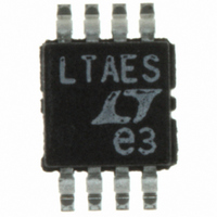
LTC6904CMS8#PBF Linear Technology, LTC6904CMS8#PBF Datasheet - Page 10

LTC6904CMS8#PBF
Manufacturer Part Number
LTC6904CMS8#PBF
Description
IC OSC PROGRAM I2C INTRFC 8-MSOP
Manufacturer
Linear Technology
Type
Oscillator, Siliconr
Datasheet
1.LTC6903CMS8.pdf
(12 pages)
Specifications of LTC6904CMS8#PBF
Frequency
68MHz
Voltage - Supply
2.7 V ~ 5.5 V
Current - Supply
7mA
Operating Temperature
-40°C ~ 85°C
Package / Case
8-MSOP, Micro8™, 8-uMAX, 8-uSOP,
Leaded Process Compatible
Yes
Rohs Compliant
Yes
Peak Reflow Compatible (260 C)
Yes
Supply Voltage Range
2.7V To 5.5V
Digital Ic Case Style
MSOP
No. Of Pins
8
Operating Temperature Range
-40°C To +85°C
Lead Free Status / RoHS Status
Lead free / RoHS Compliant
Count
-
Available stocks
Company
Part Number
Manufacturer
Quantity
Price
LTC6903/LTC6904
Typical applicaTions
LTC6904 I
The LTC6904 communicates with a host (master) using the
standard I
the timing relationship of the signals on the bus. The two
bus lines, SDA and SCL, must be high when the bus is
not in use. External pull-up resistors or current sources,
such as the LTC1694 SMBus accelerator, are required on
these lines. If the I
I
the SDA line is released during the ACK cycle to prevent
bus contention.
The LTC6904 is a receive-only (slave) device. The master
can communicate with the LTC6904 using the Write Word
protocols as explained later.
The START and STOP Conditions
When the bus is not in use, both SCL and SDA must be
high. A bus master signals the beginning of a communica-
tion to a slave device by transmitting a START condition. A
START condition is generated by transitioning SDA from
high to low while SCL is high.
When the master has finished communicating with the
slave, it issues a STOP condition. A STOP condition is
generated by transitioning SDA from low to high while
SCL is high. The bus is then free for communication with
another SMBus device.
Acknowledge
The Acknowledge signal is used for handshaking between
the master and the slave. An Acknowledge (active LOW)
0
2
C compatible device, care must be taken to ensure that
2
2
C 2-wire interface. The Timing Diagram shows
C Interface
2
C interface is not driven with a standard
S = START Condition, Wr = Write Bit = 0, A = Acknowledge, P = STOP Condition
1
S
Slave Address
Write Word Protocol Used by the LTC6904
7
Wr
1
1
A
MS Data Byte
8
generated by the slave lets the master know that the latest
byte of information was received. The Acknowledge related
clock pulse is generated by the master. The master releases
the SDA line (HIGH) during the Acknowledge clock pulse.
The slave-receiver must pull down the SDA line during the
Acknowledge clock pulse so that it remains a stable LOW
during the HIGH period of this clock pulse.
Write Word Protocol
The master initiates communication with the LTC6904
with a START condition and a 7-bit address followed by
the Write Bit (Wr) = 0. The LTC6904 acknowledges and
the master delivers the most significant data byte. Again
the LTC6904 acknowledges and the data is latched into
the most significant data byte input register. The master
then delivers the least significant data byte. The LTC6904
acknowledges once more and latches the data into the
least significant data byte input register. Lastly, the master
terminates the communication with a STOP condition.
Slave Address
The LTC6904 can respond to one of two 7-bit addresses.
The first 6 bits (MSBs) have been factory programmed
to 001011. The address pin, ADR (Pin 4) is programmed
by the user and determines the LSB of the slave address,
as shown in the table below:
1
A
LS Data Byte
ADR (Pin 4)
8
0
1
1
A
6903 AI01
1
P
LTC6904 Address
0010111
0010110
69034fc


