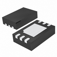
LTC6990CDCB#TRMPBF Linear Technology, LTC6990CDCB#TRMPBF Datasheet - Page 15

LTC6990CDCB#TRMPBF
Manufacturer Part Number
LTC6990CDCB#TRMPBF
Description
IC MPU SUPERVISORY 6DFN
Manufacturer
Linear Technology
Datasheet
1.LTC6990CDCBTRMPBF.pdf
(28 pages)
Specifications of LTC6990CDCB#TRMPBF
Frequency
*
Voltage - Supply
*
Current - Supply
235µA
Operating Temperature
*
Package / Case
6-WFDFN Exposed Pad
Count
*
Lead Free Status / RoHS Status
Lead free / RoHS Compliant
Other names
LTC6990CDCB#TRMPBFTR
Available stocks
Company
Part Number
Manufacturer
Quantity
Price
APPLICATIONS INFORMATION
Start-Up Behavior
When fi rst powered up, the output is high impedance. If
the output is enabled (OE = 1) at the end of the start-up
time, the output will go low for one t
a t
output is disabled (OE = 0) at the end of the start-up time,
the output will drop to a low output if the Hi-Z bit = 0, or
simply remain fl oating if Hi-Z = 1.
Basic Fixed Frequency Operation
The simplest and most accurate method to program the
LTC6990 for fi xed frequency operation is to use a single
resistor, R
procedure is a simple two step process. First select the N
value and then calculate the value for the R
Step 1: Selecting the N
As explained earlier, the voltage on the DIV pin sets the
DIVCODE which determines both the Hi-Z bit and the
N
selected to be within the following range.
To minimize supply current, choose the lowest N
(generally recommended). For faster start-up or decreased
jitter, choose a higher N
as a guide to select the best N
plication. After choosing the value for N
select the proper resistor divider or V
to the DIV pin.
Step 2: Calculate and Select R
The fi nal step is to calculate the correct value for R
using the following equation.
Select the standard resistor value closest to the calculated
value.
DIV
OUT
R
62.5kHz
SET
value. For a given output frequency, N
f
OUT
cycle if N
=
SET
1MHz • 50k
N
DIV
≤ N
, between the SET and GND pins. The design
DIV
• f
DIV
OUT
< 4) before the fi rst rising edge. If the
≤
1MHz
DIV
f
OUT
DIV
setting. Alternatively, use Table 1
Frequency Divider Value
DIV
SET
value for the given ap-
MASTER
DIV
DIV
/V
, use Table 1 to
+
SET
DIV
ratio to apply
cycle (or half
should be
resistor.
DIV
value
(1b)
(1a)
SET
DIV
Example: Design a 20kHz Oscillator with Minimum
Power Consumption
Step 1: Selecting the N
First, choose an N
of Equation (1a).
Potential settings for N
is the best choice, as it minimizes supply current by using
a large R
values to program DIVCODE to either 2 or 13, depending
on the desired behavior when the output is disabled.
Step 2: Select R
Calculate the correct value for R
Since 625k is not available as a standard 1% resistor,
substitute 619k if a 0.97% frequency shift is acceptable.
Otherwise, select a parallel or series pair of resistors such
as 309k and 316k to attain a more precise resistance.
Frequency Modulated Operation (Voltage-Controlled
Oscillator)
Operating the LTC6990 as a voltage-controlled oscillator in
its simplest form is achieved with one additional resistor. As
shown in Figure 11, voltage V
through R
lates the output frequency as described in Equation (2).
3.125 ≤ N
R
f
OUT
SET
V
CTRL
=
SET
=
VCO
N
1MHz • 50k
1MHz • 50k
Figure 11. Voltage Controlled Oscillator
4 • 20kHz
DIV
resistor. Using Table 1, choose the R1 and R2
R
DIV
VCO
to vary the I
• R
≤ 50
SET
V
DIV
VCO
+
R
SET
value that meets the requirements
DIV
OE
GND
SET
= 625k
• 1+
DIV
⎛
⎝ ⎜
LTC6990
SET
include 4, 8, 16, and 32. N
Frequency Divider Value
current, which in turn modu-
CTRL
R
R
6990 F08
OUT
DIV
VCO
SET
V
+
SET
sources/sinks a current
−
using Equation (1b).
V
V
CTRL
C1
0.1μF
LTC6990
SET
⎞
⎠ ⎟
V
+
R1
R2
15
DIV
6990f
= 4
(2)


