1-968855-1 TE Connectivity, 1-968855-1 Datasheet - Page 3
1-968855-1
Manufacturer Part Number
1-968855-1
Description
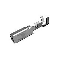
MCP2,8 SOCKET CONT SWS
Manufacturer
TE Connectivity
Series
HDSCS, J2557 Connector System, Multiple Contact Point (MCP), Standard Timerr
Specifications of 1-968855-1
Rohs Compliant
YES
Product Type
Contact
Mating Area Interface Dimensions (mm [in])
2.79 x 0.81 [.110 x .032]
Wire/cable Type
Regular Wire
Insulation Support
With
Wire Range (mm [awg])
0.50-1.00² [20-17]
Single Wire Sealing System
Yes
Single Seal Part No.
828904-1
Contact Type
Socket
Contact Base Material
CuNiSi
Contact Plating, Mating Area, Material
Pre-Tin
Rohs/elv Compliance
RoHS compliant, ELV compliant
Lead Free Solder Processes
Not relevant for lead free process
Rohs/elv Compliance History
Always was RoHS compliant
Applies To
Wire/Cable
Cavity Plug Part No.
828922
Packaging Method
Strip
Available stocks
Company
Part Number
Manufacturer
Quantity
Price
Company:

Part Number:
1-968855-1
Manufacturer:
TE
Quantity:
108 000
Company:
Part Number:
1-968855-1
Manufacturer:
SMD
Quantity:
35 000


Rev A
Free fall, cover.
Free fall, device.
Resistance to vibrations.
Mechanical shock.
Durability.
Housing locking m echanism
strength.
Test Description
Ensured functionality, som e chips
and dents perm itted but not over
seal area. Meets water tightness
test.
Ensured functionality, PDM m ounts
securely on vertical and horizontal
brackets. Som e chips and dents
perm itted but not over seal area.
Meets water tightness test.
No discontinuities greater than 1
m illisecond.
See Note.
No discontinuities greater than 1
m illisecond.
See Note.
Cover shall withstand a total of 25
m ounting-dism ounting cycles.
See Note.
Housing shall withstand
disengagem ent force of 88.96 N
[20 lbf] for 1 m inute without
depressing latches.
See Note.
Figure 1 (continued)
MECHANICAL
Requirem ent
Drop from a height of 1 m [3.28 ft]
onto a concrete floor on 3 corners
and flat on latches. Two corners at
bottom of cover (closed corners), 1
corner at seal area.
Affixed to 750 m m [29.53 in] cable
length, 40 wires m axim um , routed
sym m etrically, dropped 8 tim es
from 750 m m [29.53 in], rotated 45
degrees each tim e. Loading
configuration per Figure 3.
Two PDM units populated per
Figure 3 for vertical and horizontal
bracket m ount each, vibrated for 4
hours in each of 3 m utually
perpendicular planes per spectrum
specified in Figure 5 (GM-911P).
W ires to be strapped tight with
nylon tie wrap to respected base
end brackets, with the m axim um of
15 wires strapped to 1 end bracket.
W ires to be firm ly supported within
200 m m [7.87 in] from base wire
support brackets.
EIA 364-27B, Method H.
30 G’s, total of 18 shocks, loading
configuration per Figure 3. Rubber
inserts to be inserted to restrain
com ponents in case m echanical
shock forces exceed contact
rem oval force.
No visible hinge cracking.
EIA-364-98.
Cover latches in Test Group 2 shall
be tested by pulling axially on a
string passed through a hole drilled
in the center of the cover and
anchored inside the cover by a
m etal bar until a force of 88.96 N
[20 lbf] is attained and then held for
1 m inute. Cover latches in Test
Group 8 shall be tested to
destruction and forces recorded.
Procedure
108-47001
3 of 8
Related parts for 1-968855-1
Image
Part Number
Description
Manufacturer
Datasheet
Request
R


Part Number:
Description:
Hard Metric Connectors C42334A 347A 96=HS- BUCHSE
Manufacturer:
TE Connectivity
Datasheet:

Part Number:
Description:
96/64P FEDLEI SELEK
Manufacturer:
TE Connectivity
Datasheet:

Part Number:
Description:
Conn DIN 41612 RCP 96 POS 2.54mm Solder ST Thru-Hole
Manufacturer:
TE Connectivity
Datasheet:

Part Number:
Description:
Plug And Socket Connector Housing
Manufacturer:
TE Connectivity
Datasheet:

Part Number:
Description:
DIP SOCKET, 28POS, THROUGH HOLE
Manufacturer:
TE Connectivity
Datasheet:

Part Number:
Description:
CONTACT, SOCKET, 18-16AWG, CRIMP
Manufacturer:
TE Connectivity
Datasheet:
Part Number:
Description:
Res Thin Film 0603 1K Ohm 0.1% 1/16W ±10ppm/°C Molded SMD T/R
Manufacturer:
TE Connectivity
Datasheet:
Part Number:
Description:
Manufacturer:
TE Connectivity
Datasheet:

Part Number:
Description:
Manufacturer:
TE Connectivity
Datasheet:
Part Number:
Description:
Power to the Board 06P STR/REL & INSRT
Manufacturer:
TE Connectivity
Datasheet:

Part Number:
Description:
ADE08S04=DIP SWTCH,EXT,SMT-GW
Manufacturer:
TE Connectivity
Datasheet:
Part Number:
Description:
ADF05S04=DIP SWT,FLUSH,SMT-GW
Manufacturer:
TE Connectivity
Datasheet:
Part Number:
Description:
FSM1LPTR=NEW P/N
Manufacturer:
TE Connectivity
Datasheet: