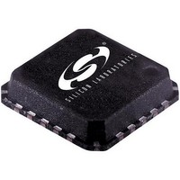
SI5310-BM Silicon Laboratories Inc, SI5310-BM Datasheet - Page 16

SI5310-BM
Manufacturer Part Number
SI5310-BM
Description
IC CLOCK MULTIPLIER/REGEN 20MLP
Manufacturer
Silicon Laboratories Inc
Type
Clock Multiplierr
Datasheet
1.SI5310-BM.pdf
(26 pages)
Specifications of SI5310-BM
Package / Case
20-VQFN Exposed Pad, 20-HVQFN, 20-SQFN, 20-DHVQFN
Pll
Yes with Bypass
Input
Clock
Output
CML
Number Of Circuits
1
Ratio - Input:output
1:2
Differential - Input:output
Yes/Yes
Frequency - Max
668MHz
Divider/multiplier
Yes/Yes
Voltage - Supply
2.375 V ~ 2.625 V
Operating Temperature
-40°C ~ 85°C
Mounting Type
Surface Mount
Frequency-max
668MHz
Mounting Style
SMD/SMT
Description/function
Multiplier/Regenratr 155MHz 622MHz
Lead Free Status / RoHS Status
Contains lead / RoHS non-compliant
Other names
336-1139
Si5310
4.11. Bias Generation Circuitry
The Si5310 makes use of an external resistor to set
internal bias currents. The external resistor allows
precise generation of bias currents which significantly
reduces power consumption compared with traditional
implementations that use an internal resistor. The bias
generation circuitry requires a 10 kΩ (1%) resistor
connected between REXT and GND.
4.12. Differential Input Circuitry
The Si5310 provides differential inputs for both the input
clock (CLKIN) and the reference clock (REFCLK)
inputs. An example termination for these inputs is
shown in Figure 6. In applications where direct dc
16
−1
−2
−3
−4
−5
−6
−7
−8
−9
0
MULTSEL = 0 (MULTOUT = 600–668 MHz)
10
Figure 4. PLL Jitter Transfer Functions,
3
CLKIN=39MHz
10
4
10
5
CLKIN=622MHz
10
6
Rev. 1.2
coupling is possible, the 0.1 µF capacitors may be
omitted. The CLKIN and REFCLK input amplifiers
require input signals with minimum differential peak-to-
peak voltages as specified in Table 2 on page 6.
4.13. Differential Output Circuitry
The Si5310 utilizes a current mode logic (CML)
architecture to output both the regenerated clock
(CLKOUT) and the multiplied clock (MULTOUT). An
example of output termination with ac coupling is shown
in Figure 10. For applications in which direct dc coupling
is possible, the 0.1 µF capacitors may be omitted. The
differential peak-to-peak voltage swing of the CML is
listed in Table 2 on page 6.
−1
−2
−3
−4
−5
−6
−7
−8
−9
MULTSEL = 1 (MULTOUT = 150–167 MHz)
0
Figure 5. PLL Jitter Transfer Functions,
10
3
CLKIN=9.7MHz
10
4
10
5
CLKIN=155MHz
10
6


