CY28442ZXC Cypress Semiconductor Corp, CY28442ZXC Datasheet - Page 3
CY28442ZXC
Manufacturer Part Number
CY28442ZXC
Description
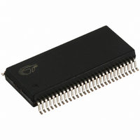
IC CLOCK GEN ALVISO 56-TSSOP
Manufacturer
Cypress Semiconductor Corp
Type
Fanout Distribution, Spread Spectrum Clock Generatorr
Datasheet
1.CY28442ZXC.pdf
(22 pages)
Specifications of CY28442ZXC
Pll
Yes with Bypass
Input
LVTTL, Crystal
Output
Clock
Number Of Circuits
1
Ratio - Input:output
11:15
Differential - Input:output
No/Yes
Frequency - Max
200MHz
Divider/multiplier
Yes/No
Voltage - Supply
3.135 V ~ 3.465 V
Operating Temperature
0°C ~ 85°C
Mounting Type
Surface Mount
Package / Case
56-TSSOP II
Frequency-max
100MHz
Lead Free Status / RoHS Status
Lead free / RoHS Compliant
Available stocks
Company
Part Number
Manufacturer
Quantity
Price

Part Number:
CY28442ZXC-2
Manufacturer:
CYP
Quantity:
20 000
Company:
Part Number:
CY28442ZXC-2T
Manufacturer:
TI
Quantity:
11
Company:
Part Number:
CY28442ZXC-4
Manufacturer:
SEMTEC
Quantity:
946


Document #: 38-07680 Rev. **
Pin Definitions
Frequency Select Pins (FS_A, FS_B and FS_C)
Host clock frequency selection is achieved by applying the
appropriate logic levels to FS_A, FS_B, FS_C inputs prior to
VTT_PWRGD# assertion (as seen by the clock synthesizer).
Upon VTT_PWRGD# being sampled low by the clock chip
(indicating processor VTT voltage is stable), the clock chip
Table 1. Frequency Select Table FS_A, FS_B and FS_C
Serial Data Interface
To enhance the flexibility and function of the clock synthesizer,
a two-signal serial interface is provided. Through the Serial
Data Interface, various device functions, such as individual
clock output buffers, can be individually enabled or disabled.
The registers associated with the Serial Data Interface
initializes to their default setting upon power-up, and therefore
use of this interface is optional. Clock device register changes
are normally made upon system initialization, if any are
required. The interface cannot be used during system
operation for power management functions.
Table 2. Command Code Definition
48
49
50
51
52
53
54
55
56
FS_C
Pin No.
(6:0)
1
0
0
0
Bit
7
FS_B
0 = Block read or block write operation, 1 = Byte read or byte write operation
Byte offset for byte read or byte write operation. For block read or block write operations, these bits should be
'0000000'
0
0
1
1
VDDA2
XOUT
XIN
VSSA2
REF1
FS_C_TEST_SEL/
REF0
CPU_STP#
PCI_STP#
PCI2/SEL_CLKREQ
(continued)
FS_A
Name
1
1
1
0
100 MHz
133 MHz
166 MHz
200 MHz
CPU
I/O, PD 3.3V-tolerant input for CLKREQ pin selection/fixed 33-MHz clock output.
O, SE 14.318-MHz crystal output.
PWR 3.3V power supply for PLL2.
GND
I, PU
I, PU
Type
I/O
ADVANCE INFORMATION
O
I
14.318-MHz crystal input.
Ground for PLL2.
Fixed 14.318 MHz clock output.
3.3V-tolerant input for CPU frequency selection/fixed 14.318 clock output.
Selects test mode if pulled to greater than 1.8V when VTT_PWRGD# is asserted
low.
Refer to DC Electrical Specifications table for V
3.3V LVTTL input for CPU_STP# active low.
3.3V LVTTL input for PCI_STP# active low.
(sampled on the VTT_PWRGD# assertion).
0= pins 32,33 function as clk request pins, 1= pins 32,33 function as SRC outputs.
100 MHz
100 MHz
100 MHz
100 MHz
SRC
Description
PCIF/PCI
samples the FS_A, FS_B and FS_C input values. For all logic
levels of FS_A, FS_B and FS_C, VTT_PWRGD# employs a
one-shot functionality in that once a valid low on
VTT_PWRGD# has been sampled, all further VTT_PWRGD#,
FS_A, FS_B and FS_C transitions will be ignored, except in
test mode.
Data Protocol
The clock driver serial protocol accepts byte write, byte read,
block write, and block read operations from the controller. For
block write/read operation, the bytes must be accessed in
sequential order from lowest to highest byte (most significant
bit first) with the ability to stop after any complete byte has
been transferred. For byte write and byte read operations, the
system controller can access individually indexed bytes. The
offset of the indexed byte is encoded in the command code,
as described in Table 2.
The block write and block read protocol is outlined in Table 3
while Table 4 outlines the corresponding byte write and byte
read protocol. The slave receiver address is 11010010 (D2h).
33 MHz
33 MHz
33 MHz
33 MHz
14.318 MHz
14.318 MHz
14.318 MHz
14.318 MHz
Description
REF0
IL_FS
96 MHz
96 MHz
96 MHz
96 MHz
DOT96
,V
IH_FS
specifications.
CY28442
Page 3 of 22
48 MHz
48 MHz
48 MHz
48 MHz
USB
[+] Feedback
Related parts for CY28442ZXC
Image
Part Number
Description
Manufacturer
Datasheet
Request
R

Part Number:
Description:
Manufacturer:
Cypress Semiconductor Corp
Datasheet:
Part Number:
Description:
Manufacturer:
Cypress Semiconductor Corp
Datasheet:
Part Number:
Description:
Manufacturer:
Cypress Semiconductor Corp
Datasheet:
Part Number:
Description:
Manufacturer:
Cypress Semiconductor Corp
Datasheet:
Part Number:
Description:
Manufacturer:
Cypress Semiconductor Corp
Datasheet: