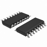
74HCT7046AD,112 NXP Semiconductors, 74HCT7046AD,112 Datasheet - Page 36

74HCT7046AD,112
Manufacturer Part Number
74HCT7046AD,112
Description
IC PLL W/LOCK DETECTOR 16SOIC
Manufacturer
NXP Semiconductors
Type
Phase Lock Loop (PLL)r
Series
74HCTr
Datasheet
1.74HC7046ADB112.pdf
(38 pages)
Specifications of 74HCT7046AD,112
Number Of Circuits
1
Package / Case
16-SOIC (3.9mm Width)
Pll
Yes
Input
Clock
Output
Clock
Ratio - Input:output
2:3
Differential - Input:output
No/No
Frequency - Max
19MHz
Divider/multiplier
No/No
Voltage - Supply
4.5 V ~ 5.5 V
Operating Temperature
-40°C ~ 125°C
Mounting Type
Surface Mount
Frequency-max
19MHz
Supply Voltage (max)
5.5 V
Supply Voltage (min)
4.5 V
Maximum Operating Temperature
+ 125 C
Minimum Operating Temperature
- 40 C
Mounting Style
SMD/SMT
Operating Supply Voltage
5 V
Lead Free Status / RoHS Status
Lead free / RoHS Compliant
Other names
74HCT7046AD
74HCT7046AD
933827490112
74HCT7046AD
933827490112
Philips Semiconductors
PLL design example
The frequency synthesizer, used in the design example
shown in Fig.34, has the following parameters:
Output frequency: 2 MHz to 3 MHz
frequency steps : 100 kHz
settling time
overshoot
The open-loop gain is H (s) x G (s) = K
Where:
The programmable counter ratio K
follows:
The VCO is set by the values of R1, R2 and C1,
R2 = 10 k (adjustable). The values can be determined
using the information in the section “DESIGN
CONSIDERATIONS”.
With f
values (V
R1 = 10 k
R2 = 10 k
C1 = 500 pF
The VCO gain is:
The gain of the phase comparator is:
The transfer gain of the filter is given by:
Where:
December 1990
K
N
K
K
K
K
K
N
K
V
p
1
max.
p
f
o
n
Phase-locked-loop with lock detector
min.
f
=
=
=
=
=
=
=
=
o
R3C2 and
--------------------------------------------- -
0.9
------------
4
------------------------------------ -
1
V
=
= 2.5 MHz and f
=
CC
+
phase comparator gain
low-pass filter transfer gain
K
1/n divider ratio
CC
---------- -
f
---------- -
f
f
2f
1
f
–
step
step
v
out
out
/s VCO gain
+
L
= 5.0 V):
=
1
V
+
CC
2
0.4 V/r.
=
=
2
s
2
: 1 ms
--------------------- -
100 kHz
--------------------- -
100 kHz
:
–
2 MHz
3 MHz
2
s
0.9
20%
=
L
R4C2.
= 500 kHz this gives the following
=
=
=
=
20
30
1 MHz
-----------------
3.2
n
can be found as
p
2
K
f
2 10
K
o
K
6
n
r/s/v
.
36
The characteristics equation is:
1 H (s) G (s) = 0.
This results in:
The natural frequency
and the damping value
The overshoot and settling time percentages are now used
to determine
damping ratio = 0.8 will produce an overshoot of less
than 20% and settle to within 5% at
settling time is 1 ms. This results in:
Rewriting the equation for natural frequency results in:
The maximum overshoot occurs at N
When C2 = 470 nF, then
R3 is calculated using the damping ratio equation:
s
R4
R3
2
n
n
+
1
1
=
=
=
+
+
=
=
1
----------------------------------------------------- s
--------- -
2
5
-- -
+
---------------------------------------------------------------- -
1
t
------- - R4
C2
2
2
K
------------------------------- -
K
n
1
=
1
p
p
=
=
–
+
-------------- -
0.001
1
----------------------------------------------------- .
1
1
K
K
------------------------------- - .
0.4 2 10
-------------------------------- -
K
˙
K
5
+
2
+
5000
+
n
p
p
v
v
. From Fig.35 it can be seen that the
K
=
2
p
2
K
K
K
K
2
=
n
2 k .
2
n
v
v
n
1
2
K
.
5 10
+
v
30
K
K
n
n
2
n
n
2
6
is defined as follows:
K
is defined as follows:
n
3
=
+
74HC/HCT7046A
–
r/s.
0.0011 s.
K
------------------------------- -
1
2
p
=
1
790
K
+
n
Product specification
v
max
t = 4.5. The required
2
K
.:
n
.
=
0.


