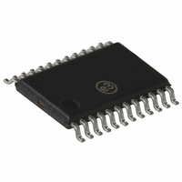
SI4112-D-GT Silicon Laboratories Inc, SI4112-D-GT Datasheet - Page 22

SI4112-D-GT
Manufacturer Part Number
SI4112-D-GT
Description
IC SYNTHESIZER IF ONLY 24TSSOP
Manufacturer
Silicon Laboratories Inc
Type
Frequency Synthesizerr
Datasheet
1.SI4112-D-GT.pdf
(36 pages)
Specifications of SI4112-D-GT
Number Of Circuits
1
Package / Case
24-TSSOP
Pll
Yes
Input
Clock
Output
Clock
Ratio - Input:output
1:2
Differential - Input:output
No/No
Frequency - Max
1GHz
Divider/multiplier
Yes/No
Voltage - Supply
2.7 V ~ 3.6 V
Operating Temperature
-40°C ~ 85°C
Mounting Type
Surface Mount
Frequency-max
1GHz
Maximum Input Frequency
62.5 MHz to 1000 MHz
Minimum Input Frequency
2 MHz
Supply Voltage (max)
3.6 V
Supply Voltage (min)
2.7 V
Maximum Operating Temperature
+ 85 C
Minimum Operating Temperature
- 40 C
Mounting Style
SMD/SMT
Operating Supply Voltage
2.7 V to 3.6 V
Lead Free Status / RoHS Status
Lead free / RoHS Compliant
Lead Free Status / RoHS Status
Lead free / RoHS Compliant, Lead free / RoHS Compliant
Other names
336-1171
Si4133
Register 0. Main Configuration Address Field = A[3:0] = 0000
22
Name
Bit
17:14
13:12
11:10
Bit
9:6
5
4
3
2
1
0
D17 D16 D15 D14 D13 D12 D11 D10 D9
0
0
AUXSEL
AUTOPDB
IFDIV
Reserved
Reserved
Reserved
Reserved
AUTOK
RFPWR
0
LPWR
Name
[1:0]
0
[1:0]
P
AUXSEL
[1:0]
Auxiliary Output Pin Definition.
00 = Reserved.
01 = Force output low.
10 = Reserved.
11 = Lock Detect—LDETB.
IF Output Divider.
00 = IFOUT = IFVCO Frequency
01 = IFOUT = IFVCO Frequency/2
10 = IFOUT = IFVCO Frequency/4
11 = IFOUT = IFVCO Frequency/8
Output Power-Level Settings for IF Synthesizer Circuit.
0 = R
1 = R
Auto Powerdown.
0 = Software powerdown is controlled by Register 2.
1 = Equivalent to setting all bits in Register 2 = 1.
Auto K
0 = K
1 = K
Program to zero. (Used for extended frequency operation. See AN41 for
more information.)
Program to zero.
Program to zero.
Program to zero.
Program to zero.
P
P
LOAD
LOAD
s are controlled by Register 1.
s are set according to Table 9 on page 18.
IFDIV
P
[1:0]
Setting.
500 —normal power mode.
500 —low power mode.
Rev. 1.61
0
D8
0
D7
0
Function
D6
0
LPWR
D5
D4
0
AUTO
PDB
D3
AUTO
D2
K
P
PWR
D1
RF
D0
0


