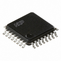
PCK9448BD,157 NXP Semiconductors, PCK9448BD,157 Datasheet - Page 13

PCK9448BD,157
Manufacturer Part Number
PCK9448BD,157
Description
IC FANOUT BUFFER 1:12 32LQFP
Manufacturer
NXP Semiconductors
Type
Fanout Buffer (Distribution), Multiplexerr
Datasheet
1.PCK9448BD157.pdf
(20 pages)
Specifications of PCK9448BD,157
Number Of Circuits
1
Ratio - Input:output
2:12
Differential - Input:output
Yes/Yes
Input
LVCMOS, LVPECL
Output
LVCMOS
Frequency - Max
350MHz
Voltage - Supply
2.375 V ~ 3.465 V
Operating Temperature
-40°C ~ 85°C
Mounting Type
Surface Mount
Package / Case
32-LQFP
Frequency-max
350MHz
Lead Free Status / RoHS Status
Lead free / RoHS Compliant
Other names
568-3566
935280284157
PCK9448BD
935280284157
PCK9448BD
Available stocks
Company
Part Number
Manufacturer
Quantity
Price
Company:
Part Number:
PCK9448BD,157
Manufacturer:
NXP Semiconductors
Quantity:
10 000
Philips Semiconductors
9397 750 12534
Product data sheet
P
f
T
+
In
V
signal duty cycle. If transmission lines are used, C
eliminated. In general, the use of controlled transmission line techniques eliminates the
impact of the lumped capacitive loads at the end lines and greatly reduces the power
dissipation of the device.
function of the power consumption.
Where R
the ambient temperature. According to
estimate the long-term device reliability. Further, combining
results in a maximum operating frequency for the PCK9448 in a series terminated
transmission line system,
T
R
using 2S2P boards will result in a lower thermal impedance than indicated below.
Table 11:
If the calculated maximum frequency is below 350 MHz, it becomes the upper clock speed
limit for the given application conditions. The following four derating charts describe the
safe frequency operation range for the PCK9448. The charts were calculated for a
maximum tolerable die junction temperature of 110 C (120 C), corresponding to an
estimated MTBF of 9.1 years (4 years), a supply voltage of 3.3 V and series terminated
transmission line or capacitive loading. Depending on a given set of these operating
conditions and the available device convection, a decision on the maximum operating
frequency can be made.
Convection (LFPM)
still air
100
200
300
400
500
clk max
tot
j(max)
OL
j
th(j-a)
P
Equation
=
, I
=
T
OL
o
V
should be selected according to the MTBF system requirements and
can be derived from
amb
, V
CC
=
th(j-a)
I
OH
OH
+
Thermal package impedance of the LQFP32
---------------------------------------- -
C
2, P stands for the number of outputs with a parallel or Thevenin termination;
P
PD
and I
is the thermal impedance of the package (junction-to-ambient) and T
I
tot
q max
V
N
CC
1
R
OH
th j-a
+
Rev. 01 — 29 November 2005
–
V
are a function of the output termination technique;
V
V
CC
CC
OH
Equation 3
2
Equation
Table
+
f
T
----------------------------------- -
R
88
76
71
68
66
60
clk
1 DC
j max
th(j-a)
–
11. The R
R
th j-a
4.
N
( C/W) (1P2S board)
describes the die junction temperature T
–
Q
Table
T
3.3 V/2.5 V LVCMOS 1 : 12 clock fan-out buffer
C
amb
PD
I
th(j-a)
OL
–
+
10, the junction temperature can be used to
I
M
q max
represent data based on 1S2P boards;
V
C
OL
L
L
is zero in
V
CC
© Koninklijke Philips Electronics N.V. 2005. All rights reserved.
Equation 1
R
61
56
54
53
52
49
th(j-a)
Equation 2
( C/W) (2P2S board)
PCK9448
and
o
and can be
is the clock
Equation 2
Table
j
as a
10.
amb
13 of 20
is
(2)
(3)
(4)


