PAXLHV00 Red Lion Controls, PAXLHV00 Datasheet - Page 5
PAXLHV00
Manufacturer Part Number
PAXLHV00
Description
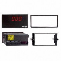
METER AC VOLT 3-DIGIT PNL MNT
Manufacturer
Red Lion Controls
Series
PAX®LITEr
Type
Voltmeterr
Datasheet
1.PAXLHV00.pdf
(8 pages)
Specifications of PAXLHV00
Measuring Range
0 ~ 600VAC
Display Style
Red Characters, Black Background
Display Type
LED
Display Face Size
3.80" L x 1.95" W (96.5 x 49.5mm)
Display Digits
3
Display Digits - Height
0.560" (14.22mm)
Backlight
Without
Mounting Type
Panel Mount
Termination
Terminal Block
Voltage - Supply
115VAC,230 VAC
No. Of Digits / Alpha
3
Meter Function
AC Voltmeter
Meter Range
0V To 600V
Digit Height
14.2mm
Power Consumption
6VA
Operating Temperature Range
0°C To +60°C
Supply Voltage Ac, Min
115V
Character Size
0.56"
Display Font Color
Red
Rohs Compliant
NA
Lead Free Status / RoHS Status
Lead free / RoHS Compliant
Other names
RLC111


WIRING OVERVIEW
cabling should conform to appropriate standards of good installation, local codes
and regulations. It is recommended that power supplied to the unit be protected
by a fuse or circuit breaker. As depicted in the drawing of the Model PAXLHV,
all connections are made on the terminal block located at the rear of the unit.
EMC INSTALLATION GUIDELINES
Electromagnetic Interference (EMI), proper installation and wiring methods
must be followed to ensure compatibility in each application. The type of the
electrical noise, source or coupling method into the meter may be different for
various installations. Cable length, routing and shield termination are very
important and can mean the difference between a successful or a troublesome
installation. Listed below are some EMC guidelines for successful installation
in an industrial environment.
1. The meter should be mounted in a metal enclosure, that is properly connected
2. Use shielded (screened) cables for all Signal and Control inputs. The shield
3. Never run Signal or Control cables in the same conduit or raceway with AC
3.1 POWER WIRING
located on the left-hand side of the terminal block). For best results, the AC
power should be relatively “Clean” and within the specified ±10% variation
limit. Drawing power from heavily loaded circuits or from circuits that also
power loads that cycle on and off, should be avoided.
3.0 W
All conductors should meet voltage and current ratings for each terminal. Also,
Although this meter is designed with a high degree of immunity to
to protective earth.
(screen) pigtail connection should be made as short as possible. The
connection point for the shield depends somewhat upon the application.
Listed below are the recommended methods of connecting the shield, in order
of their effectiveness.
a. Connect the shield only at the panel where the meter is mounted to earth
b. Connect the shield to earth ground at both ends of the cable, usually when
c. Connect the shield to common of the meter and leave the other end of the
power lines, conductors feeding motors, solenoids, SCR controls, and
heaters, etc. The cables should be run in metal conduit that is properly
grounded. This is especially useful in applications where cable runs are long
and portable two-way radios are used in close proximity or if the installation
is near a commercial radio transmitter.
Primary AC power is connected to terminal 1 and 2 (Marked AC Power,
AC Power
Terminal 1: VAC
Terminal 2: VAC
ground (protective earth).
the noise source frequency is above 1 MHz.
shield unconnected and insulated from earth ground.
IRING THE
115/230
1
2
M
ETER
5
4. Signal or Control cables within an enclosure should be routed as far as possible
5. In extremely high EMI environments, the use of external EMI suppression
6. Long cable runs are more susceptible to EMI pickup than short cable runs.
3.2 INPUT SIGNAL WIRING
PAXLHV with the same voltage that is being measured, terminal 5 (COMM.)
should be connected to neutral for the most stable reading on the display. If an
unstable display results from measuring a voltage that is isolated from the supply
voltage, reversing the supply voltage connections may correct this condition.
(NEUTRAL)
COMMON
600VAC
from contactors, control relays, transformers, and other noisy components.
devices, such as ferrite suppression cores, is effective. Install them on Signal
and Control cables as close to the unit as possible. Loop the cable through the
core several times or use multiple cores on each cable for additional protection.
Install line filters on the power input cable to the unit to suppress power line
interference. Install them near the power entry point of the enclosure. The
following EMI suppression devices (or equivalent) are recommended:
Therefore, keep cable runs as short as possible.
Input connections are made on terminal 5 and 8. When powering the
(HOT)
Voltage Input
Terminal 5: Common
Terminal 8: 600 VAC
Ferrite Suppression Cores for signal and control cables:
Line Filters for input power cables:
Note: Reference manufacturer's instructions when installing a line filter.
Fair-Rite # 0443167251 (RLC #FCOR0000)
TDK # ZCAT3035-1330A
Steward #28B2029-0A0
Schaffner # FN610-1/07 (RLC #LFIL0000)
Schaffner # FN670-1.8/07
Corcom #1VB3
Corcom #1VR3
2
5
8
1
The PAX Lite AC Voltage Monitor incorporates a built-in precision
voltage divider that provides direct measurement from 0 to 600 VAC.
1M
BLOCK DIAGRAM
SUPPLY
POWER
ADJUSTMENT
CALIBRATION
SHAPING
CIRCUIT
WAVE
600V MAX. AC
5
+V
V
8
DISPLAY