PAXLHV00 Red Lion Controls, PAXLHV00 Datasheet - Page 4
PAXLHV00
Manufacturer Part Number
PAXLHV00
Description
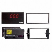
METER AC VOLT 3-DIGIT PNL MNT
Manufacturer
Red Lion Controls
Series
PAX®LITEr
Type
Voltmeterr
Datasheet
1.PAXLHV00.pdf
(8 pages)
Specifications of PAXLHV00
Measuring Range
0 ~ 600VAC
Display Style
Red Characters, Black Background
Display Type
LED
Display Face Size
3.80" L x 1.95" W (96.5 x 49.5mm)
Display Digits
3
Display Digits - Height
0.560" (14.22mm)
Backlight
Without
Mounting Type
Panel Mount
Termination
Terminal Block
Voltage - Supply
115VAC,230 VAC
No. Of Digits / Alpha
3
Meter Function
AC Voltmeter
Meter Range
0V To 600V
Digit Height
14.2mm
Power Consumption
6VA
Operating Temperature Range
0°C To +60°C
Supply Voltage Ac, Min
115V
Character Size
0.56"
Display Font Color
Red
Rohs Compliant
NA
Lead Free Status / RoHS Status
Lead free / RoHS Compliant
Other names
RLC111


Installation
unit is intended to be mounted into an enclosed panel. Prepare the panel cutout
to the dimensions shown. Remove the panel latch from the unit. Slide the panel
BEZEL
applying power. To access the switch, remove the meter base from the case by
firmly squeezing and pulling back on the side rear finger tabs. This should lower
the latch below the case slot (which is located just in front of the finger tabs). It
is recommended to release the latch on one side, then start the other side latch.
Power Selection Switch
Set-Up DIP Switches
points and backlight annunciator. Selecting the “ON” position enables the
function.
1.0 I
2.0 S
The PAX meets NEMA 4X/IP65 requirements when properly installed. The
The meter has a switch, which must be checked and/or changed prior to
A DIP switch is located inside the meter. It is used for the selection of decimal
PANEL
GASKET
SWITCH
proper voltage before powering-up the meter. The meter is shipped
from the factory in the 230 VAC position.
1
2
3
4
Caution: Insure the AC power selection switch is set for the
NSTALLING THE
ETTING THE
LATCHING
SLOTS
Backlight Annunciator for Units Label
Decimal Point 1 (000.0)
Decimal Point 2 (00.00)
Decimal Point 3 (0.000)
gasket over the rear of the unit to the back
of the bezel. The unit should be installed
FUNCTION
PANEL
fully assembled. Insert the unit
into the panel cutout.
PANEL
MOUNTING
SCREWS
S
WITCHES
PANEL
LATCH
M
LATCHING
TABS
ETER
4
so that the tabs of the panel latch engage in the slots on the case. The panel latch
should be engaged in the farthest forward slot possible. To achieve a proper seal,
tighten the latch screws evenly until the unit is snug in the panel (Torque to
approximately 7 in-lbs [79N-cm]). Do not over-tighten the screws.
Installation Environment
operating temperature and provides good air circulation. Placing the unit near
devices that generate excessive heat should be avoided.
Do NOT use solvents. Continuous exposure to direct sunlight may accelerate the
aging process of the bezel.
While holding the unit in place, push the panel latch over the rear of the unit
The unit should be installed in a location that does not exceed the maximum
The bezel should be cleaned only with a soft cloth and neutral soap product.
3.62
(92
PANEL CUT-OUT
+.03
+.8
-.00
-.0
)
1.77
(45
ON
+.02
+.5
-.00
-.0
4
)
3
2
1