LD400400 Red Lion Controls, LD400400 Datasheet - Page 8
LD400400
Manufacturer Part Number
LD400400
Description
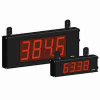
COUNTER 4 DIGIT 4.0" 120VAC RED
Manufacturer
Red Lion Controls
Series
LDr
Type
Counterr
Specifications of LD400400
Count Rate
35kHz
Number Of Digits/alpha
4
Input Type
Voltage
Voltage - Supply
11 V ~ 16 VDC, 85 V ~ 250 VAC
Display Type
LED Red
No. Of Digits / Alpha
4
Digit Height
101mm
Power Consumption
26VA
Counting Speed
25kHz
Operating Temperature Range
0°C To +50°C
Signal Input Type
Pulse
Character Size
4"
Ip/nema Rating
IP65 / NEMA 4X
Connection Type
Wire Leads
Dimensions
20"L×2.25"W×7.875"H
Display Digit Height
4 "
Function
Counter
Material, Casing
Aluminum
Number Of Digits
6
Primary Type
Electronic
Special Features
RS485/RS232 Communications
Termination
Terminal Block
Voltage, Supply
85 to 250/11 to 16 VAC/VDC
Counter Supply Voltage
85-250VAC/11-16VDC
Rohs Compliant
Yes
Lead Free Status / RoHS Status
Lead free / RoHS Compliant
Output Type
-
Lead Free Status / Rohs Status
RoHS Compliant part
Other names
RLC118


affect Counter B scale factor calculations.
enter a negative Count Load value, increment digit 6 to display a “-” sign.*
activations of the selected setpoint(s). The count source for the batch counter
can be SP1, SP2 or both. Batch counting is available in all count modes except
Dual Counter, which uses an external input signal for Counter B.
obtain the desired process value. A scale factor of 1.0000 will result in the
display of the actual number of input or batch counts. (Details on scaling
calculations are explained at the end of this section.)*
SCALING FOR COUNT INDICATION
display for each pulse that is input to the unit. In many applications, there will
not be a one-to-one correspondence between input pulses and display units.
Therefore, it is necessary for the meter to scale or multiply the input pulses by
a scale factor to achieve the desired display units (feet, meters, gallons, etc.)
important to note that the precision of a counter application cannot be improved
by using a scale factor greater than one. To accomplish greater precision, more
pulse information must be generated per measuring unit. The following formula
is used to calculate the scale factor.
WHERE:
Desired Display Units: Count display units acquired after pulses that occurred.
Decimal Point Position:
Number of Pulses: Number of pulses required to achieve the desired
This selects the decimal point position for Counter B. The selection will also
Counter A resets to this value if Reset to Count Load action is selected. To
The Counter B Batch Count function internally counts the number of output
The number of input or batch counts is multiplied by the scale factor to
The selected counter(s) will reset at each meter power-up.
The counter’s scale factor is factory set to 1, to provide one count on the
The Count Scale Factor Value can range from 00.0001 to 99.9999. It is
Scale Factor = Desired Display Units x Decimal Point Position
0
0.0
0.00
0.000
0.0000
COUNTER B DECIMAL POINT POSITION
=
=
=
=
=
COUNTER B BATCH COUNT ENABLE
COUNTER A COUNT LOAD VALUE
COUNTER RESET AT POWER-UP
COUNTER B SCALE FACTOR
Number of Pulses
1
10
100
1000
10000
display units.
to
to
8
EXAMPLE: The counter display is used to indicate the total number of feet
hundredth resolution.
user input selection perfroms a Reset, Inhibit or Store function on one or both
of the counters.
*For value entry instructions, refer to selection/value entry in the Programming
mode or batch counter).
* Indicates Edge Triggered function. All others are Level Active functions.
used in a process. It is necessary to know the number of pulses for the desired
units to be displayed. The decimal point is selected to show the resolution in
hundredths.
Scale Factor = Desired Display Units x Decimal Point Position
Given that 128 pulses are equal to 1 foot, display total feet with a one-
Scale Factor = 1.00 x 100
Scale Factor = 0.007812 x 100
Scale Factor = 0.7812
The User Input Assignment is only active when Counter B is enabled and the
The Meter section.
Shaded area selections only apply when Counter B is enabled (Dual Count
DISPLAY
No Function
Program Mode Lock-out
Inhibit
Maintained Reset
Store
Store and Reset
Display Select *
Display Intensity Level *
Setpoint 1 Reset *
Setpoint 2 Reset *
Setpoint 1 and 2 Reset *
Print Request
Print and Reset *
128
USER INPUT ASSIGNMENT
Number of Pulses
USER INPUT FUNCTION
MODE
DESCRIPTION
User Input disabled.
See Programming Mode
Access chart (Module 3).
Inhibit counting for the
selected counter(s).
Level active reset of the
selected counter(s).
Freeze display for the selected
counter(s) while allowing
counts to accumulate internally.
Edge triggered reset of the
selected counter(s) after
storing the count.
Advance once for each
activation.
Increase intensity one level
for each activation.
Reset setpoint 1 output.
Reset setpoint 2 output.
Reset both setpoint 1 and 2
outputs.
Serial transmit of the active
parameters selected in the Print
Options menu (Module 5).
Same as Print Request followed
by a momentary reset of the
selected counter(s).