LD400400 Red Lion Controls, LD400400 Datasheet - Page 6
LD400400
Manufacturer Part Number
LD400400
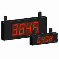
Description
COUNTER 4 DIGIT 4.0" 120VAC RED
Manufacturer
Red Lion Controls
Series
LDr
Type
Counterr
Specifications of LD400400
Count Rate
35kHz
Number Of Digits/alpha
4
Input Type
Voltage
Voltage - Supply
11 V ~ 16 VDC, 85 V ~ 250 VAC
Display Type
LED Red
No. Of Digits / Alpha
4
Digit Height
101mm
Power Consumption
26VA
Counting Speed
25kHz
Operating Temperature Range
0°C To +50°C
Signal Input Type
Pulse
Character Size
4"
Ip/nema Rating
IP65 / NEMA 4X
Connection Type
Wire Leads
Dimensions
20"L×2.25"W×7.875"H
Display Digit Height
4 "
Function
Counter
Material, Casing
Aluminum
Number Of Digits
6
Primary Type
Electronic
Special Features
RS485/RS232 Communications
Termination
Terminal Block
Voltage, Supply
85 to 250/11 to 16 VAC/VDC
Counter Supply Voltage
85-250VAC/11-16VDC
Rohs Compliant
Yes
Lead Free Status / RoHS Status
Lead free / RoHS Compliant
Output Type
-
Lead Free Status / Rohs Status
RoHS Compliant part
Other names
RLC118


RS232 Communications
50 feet. Data Terminal Equipment (DTE) transmits data on the Transmitted Data
(TXD) line and receives data on the Received Data (RXD) line. Data Computer
Equipment (DCE) receives data on the TXD line and transmits data on the RXD
line. The LD emulates a DTE. If the other device connected to the meter also
emulates a DTE, the TXD and RXD lines must be interchanged for
communications to take place. This is known as a null modem connection. Most
printers emulate a DCE device while most computers emulate a DTE device.
without a pause in between. In these cases, the meter employs a busy function.
determine if the receiving device is “busy”. The receiving device asserts that it
is busy by setting the RXD line to a space condition (logic 0). The meter then
suspends transmission until the RXD line is released by the receiving device.
Sections 4 and 5 apply to Programmable Models Only
4.0 R
5.0 P
PROGRAMMING MODE ENTRY (PAR KEY)
installation. The meter normally operates in the Display Mode. No parameters
can be programmed in this mode. The Programming Mode is entered by
pressing the
code or a hardware lock.
between the rate and count values.
RS232 is intended to allow two devices to communicate over distances up to
Some devices cannot accept more than two or three characters in succession
As the meter begins to transmit data, the RXD line (RS232) is monitored to
It is recommended all programming changes be made off line, or before
OPERATING MODE DISPLAY DESIGNATORS
Pressing the
LD METER (DTE)
“
“
”
”
- To the left of the display is the Counter B value (dual count or batch).
- To the left of the display is the rate value.
- Counter A has no designator.
PAR
SEL
key. If it is not accessible, then it is locked by either a security
ROGRAMMING THE
Terminal Block Connection Figure
EVIEWING THE
key toggles the meter through the selected displays. If display scroll is enabled, the display will toggle automatically every four seconds
1
2
3
SEL
RST
KEY
TXD
RXD
COMM.
PAR
DISPLAY
PAR
Pro
MODE
NO
DISPLAY MODE OPERATION
Access Programming Mode
Index display through selected displays
Resets count display(s) and/or outputs
RXD
TXD
Input Setup
Parameters
SEL
1-INP
PAR
RECEIVING DEVICE
DB25
DCE
2
3
5
DB25
DTE
3
2
7
PROGRAMMING MENU
F
Parameters
Rate Setup
2-rAtE
DB9
DTE
RONT
2
3
5
OVERVIEW
PAR
M
Display and Front
6
ETER
Parameters
PROGRAMMING MODE OPERATION
Store selected parameter and index to next parameter
Advance through selection list/select digit position in
parameter value
Increment selected digit position of parameter value
Panel Key
3-dSP
RS485 Communications
devices on a single pair of wires, distances up to 4,000 ft. and data rates as high
as 10M baud (the LD is limited to 38.4k baud). The same pair of wires is used
to both transmit and receive data. RS485 is therefore always half-duplex, that is,
data cannot be received and transmitted simultaneously.
P
MODULE ENTRY (SEL & PAR KEYS)
together parameters that are related in function. The display will alternate between
The displayed module is entered by pressing the
“
“
1
2
The RS485 communication standard allows the connection of up to 32
The Programming Menu is organized into five modules. These modules group
ANEL
”
”
and the present module. The
Transmit
Enable
PAR
- To the right of digit 6 indicates setpoint 1 output status.
- To the right of digit 1 indicates setpoint 2 output status.
LD METER
Parameters
Terminal Block Connection Figure
4-SPt
+5V
Setpoint
K
Output
47K
47K
PAR
EYS AND
SEL
5
4
3
B (-)
A (+)
COMM.*
Parameters
key is used to select the desired module.
5-SEr
Setup
Serial
PAR
RECEIVING DEVICE
PAR
* OPTIONAL
D
key.
ISPLAY