E5GN-Q1TD AC/DC24 Omron, E5GN-Q1TD AC/DC24 Datasheet - Page 15
E5GN-Q1TD AC/DC24
Manufacturer Part Number
E5GN-Q1TD AC/DC24
Description
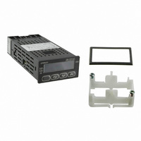
CONTROL TEMP DGTL VOLT OUT 24V
Manufacturer
Omron
Type
Digital Temperature Controllerr
Specifications of E5GN-Q1TD AC/DC24
Analog / Digital
Digital
Control Method
ON/OFF
Voltage Rating
24 VAC, 24 VDC
Mounting
Panel
Display Type
11-Segment, 4 Digit
Size
99 mm x 48 mm x 35 mm
Features
Compatible with Support Software (CX-Thermo version 4.2 or higher)
Input Type
Thermocouple
Output Type
Voltage
Operating Temperature Max
55°C
Operating Temperature Min
-10°C
Temperature Accuracy ±
0.2%
Output Voltage Max
13.8VDC
Output Voltage Min
10.2VDC
Meter Function
Thermocouple
Thermocouple Type
J, K, T, E, L, U, N, R, S, B, W, PLII
Rohs Compliant
Yes
Lead Free Status / RoHS Status
Lead free / RoHS Compliant
Lead Free Status / RoHS Status
Lead free / RoHS Compliant, Lead free / RoHS Compliant
Other names
E5GNQ1TDACDC24
Z3048
Z3048


Communications Setting Level
Set the E5GN communications specifications in the communications setting level. For setting communications parameters, use the E5GN panel.
The communications parameters and their settings are listed in the following table.
Note: The highlighted values indicate default settings.
Before executing communications with the E5GN, set the communi-
cations unit No., baud rate, etc., through key operations as described
below. As for other operations, refer to relevant Operation Manual.
1. Press the
2. Press the
3. Pressing the
4. Press the
Note: On the E5GN, the
Set each communications parameter to match those of the communi-
cating personal computer.
Troubleshooting
When an error occurs, an error code will be displayed on the No. 1 display. Check the contents of an error and take appropriate countermeasures.
Note 1. If the input is within the range for which control is possible but outside the displayable range (–1999 (–199.9) to 9999 (999.9)),
Communications unit No.
Baud rate
Data bits
Stop bits
Parity
s.err (S. Err)
e111 (E111)
h.err (H. Err)
level.” The level moves to the “initial setting level.”
level” moves to the “communications setting level.”
following figure.
No.1 display
2. These errors are displayed only when the Controller is set to display the present value or the present value and the set value. They are not
be displayed if the value is less than –1999 (–199.9), and
output will operate normally for either of these displays. Refer to the relevant User’s Manual for details on the ranges for which control is
possible.
displayed in other statuses.
Parameter
key for less than one second. The “initial setting
key for at least three seconds in the “operation
or
Input error (See note.)
A/D converter error
(See note.)
Memory error
HB error (See note.)
u-no
sbit
prty
bps
len
key advances the parameters as shown in the
keys to change the parameter setups.
e?en
Key is the
9.6
Contents
1
7
2
Communications
unit No.
Baud rate
Data bits
Stop bits
Communications
parity
u-no
bps
len
sbit
prty
Displayed characters
Key.
Check that the input wiring is correct, that there is no discon-
nection or short-circuit, and that the input type is correct.
(Thermocouple input short-circuits cannot be detected.)
After noting the error, reset the power. If the display does not
change, replacement is necessary. If the error is removed, it
is possible that the original error was caused by noise. Check
that there are no possible sources of noise.
Reset the power. If the display does not change, replacement
is necessary. If the error is removed, it is possible that the
original error was caused by noise. Check that there are no
possible sources of noise.
cccc
Countermeasure
will be displayed if it is greater than 9999 (999.9). Control output and alarm
0 to 99
1.2/2.4/4.8/9.6/19.2 (kbps)
7/8 (bit)
1/2
None, even, odd
Communications Unit No. (u-no)
When communicating with the host computer, the unit number must
be set in each Temperature Controller so that the host computer can
identify each Temperature Controller. The number can be set in a
range from 0 to 99 in increments of 1. The default setting is 1. When
using more than one Unit, be careful not to use the same number
twice. Duplicate settings will cause malfunction. This value becomes
valid when the power is turned OFF and ON again.
Baud Rate (bps)
Use this parameter to set the speed of communications with the host
computer. It can be set to one of the following values; 1.2 (1200 bps),
2.4 (2400 bps), 4.8 (4800 bps), 9.6 (9600 bps), and 19.2
(19200 bps).
This setting becomes valid when the power is turned OFF and ON
again.
Data Bits (len)
Use this parameter to change the communications data bit length to
7 bits or 8 bits.
Stop Bits (sbit)
Use this parameter to change the communications stop bit to 1 or 2.
Communications Parity (prty)
Use this parameter to set the communications parity to None, Even,
or Odd.
Digital Temperature Controllers
Set (monitor) value
0.1
1.2/2.4/4.8/9.6/19.2
1/2
none/eVen/odd
7/8 (bit)
OFF
OFF
OFF
OFF
Control output
to 99
(bit)
E5GN
Output status
Set value
Handled as ab-
normally high
temperature
OFF
OFF
OFF
Alarm output
cccc
15
will