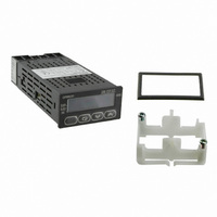
E5GN-Q1TD AC/DC24 Omron, E5GN-Q1TD AC/DC24 Datasheet - Page 5

E5GN-Q1TD AC/DC24
Manufacturer Part Number
E5GN-Q1TD AC/DC24
Description
CONTROL TEMP DGTL VOLT OUT 24V
Manufacturer
Omron
Type
Digital Temperature Controllerr
Specifications of E5GN-Q1TD AC/DC24
Analog / Digital
Digital
Control Method
ON/OFF
Voltage Rating
24 VAC, 24 VDC
Mounting
Panel
Display Type
11-Segment, 4 Digit
Size
99 mm x 48 mm x 35 mm
Features
Compatible with Support Software (CX-Thermo version 4.2 or higher)
Input Type
Thermocouple
Output Type
Voltage
Operating Temperature Max
55°C
Operating Temperature Min
-10°C
Temperature Accuracy ±
0.2%
Output Voltage Max
13.8VDC
Output Voltage Min
10.2VDC
Meter Function
Thermocouple
Thermocouple Type
J, K, T, E, L, U, N, R, S, B, W, PLII
Rohs Compliant
Yes
Lead Free Status / RoHS Status
Lead free / RoHS Compliant
Lead Free Status / RoHS Status
Lead free / RoHS Compliant, Lead free / RoHS Compliant
Other names
E5GNQ1TDACDC24
Z3048
Z3048
Models with Analog Inputs
Models with One Control Output and a 100 to 240-VAC Power Supply (Add AC100240 to the Model number.)
Note: Models with analog inputs do not display the temperature unit.
*1. If heating/cooling control mode is used, an auxiliary output is used as a control output for the cooling side. The number of auxiliary outputs that
*2. A current control output can be used as the transfer output. In that case, an auxiliary output is used as the control output. (This is not possible
Models with One Control Output and a 24-VAC/VDC Power Supply (Add ACDC24 to the Model number.)
*1. If heating/cooling control mode is used, an auxiliary output is used as a control output for the cooling side. The number of auxiliary outputs that
*2. A current control output can be used as the transfer output. In that case, an auxiliary output is used as the control output. (This is not possible
Black
Black
Case color
Case color
can be used will decrease by one. Also, the signal for the control output for the cooling side will be a relay output.
for models without an auxiliary output.) The control output will be a relay output. The number of auxiliary outputs that can be used will decrease
by one.
can be used will decrease by one. Also, the signal for the control output for the cooling side will be a relay output.
for models without an auxiliary output.) The control output will be a relay output. The number of auxiliary outputs that can be used will decrease
by one.
Relay output
Voltage
output (for
driving SSR)
Current
output
Relay output
Voltage
output (for
driving SSR)
Current
output
Control
Control
output
output
Standard or
heating/
cooling
Standard or
heating/
cooling
mode *1
mode *1
Control
Control
1
1
auxiliary
auxiliary
outputs
outputs
No. of
No. of
Detection of
---
Detection of
---
SSR failure,
overcurrent
SSR failure,
overcurrent
and heater
and heater
burnout,
burnout,
heater
heater
No. of event
---
No. of event
---
inputs
inputs
---
Transfer
output using
control
output
---
Transfer
output using
control
output
output *2
output *2
Transfer
Transfer
RS-485
---
RS-485
---
Communi-
Communi-
cations
cations
Thermocou-
---
---
---
Thermocou-
---
---
---
ple input
ple input
Previous model
Previous model
---
---
---
---
---
---
Resistance
Resistance
thermome-
thermome-
ter input
ter input
E5GN-
R103L-FLK
E5GN-
Q103L-FLK
E5GN-C1L
E5GN-
R103LD-FLK
E5GN
-Q103LD-FLK
E5GN-C1LD
New model
New model
E5GN
5


