E5CN-R2MT-500 AC100-240 Omron, E5CN-R2MT-500 AC100-240 Datasheet - Page 19
E5CN-R2MT-500 AC100-240
Manufacturer Part Number
E5CN-R2MT-500 AC100-240
Description
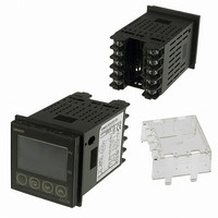
CONTROL TEMP DIGITAL HEAT/COOL
Manufacturer
Omron
Series
E5CN-Tr
Type
Temperature Controller, Digitalr
Specifications of E5CN-R2MT-500 AC100-240
Input Type
RTD, Thermocouple (Multiple)
Controller Type
On/Off or Proportional (PID)
Temperature Range
Selectable, Varies By Input Type
Output Type
Relay
Supply Voltage
100 ~ 240VAC
Size
48mm W x 48mm H (1/16 DIN)
Features
Terminal Cover
Display Type
4 Digit (2)
Operating Temperature Max
55°C
Operating Temperature Min
-10°C
Temperature Accuracy ±
0.5%
Output Voltage Max
240VAC
Output Voltage Min
5V
Controller Input
Thermocouple Or RTD
Thermocouple Type
J, K, T, E, L, U, N, R, S, B, W, PLII
Rohs Compliant
Yes
Lead Free Status / RoHS Status
Lead free / RoHS Compliant
Communications
-
Lead Free Status / RoHS Status
Lead free / RoHS Compliant, Lead free / RoHS Compliant
Other names
E5CN-R2MT-500-AC100240
E5CNR2MT500AC100240
Z2409
E5CNR2MT500AC100240
Z2409


Advanced Type
Some parameters are not displayed
depending on the model of the Controller and
parameter settings.
For details, refer to the E5CN-H/E5AN-H/
E5EN-H Digital Controllers User's Manual
Advanced Type (Cat. No. H157).
c
c
http://www.ia.omron.com/
1.olh
1.lba
1.csc
1.oll
1.aut
d.pid
1320.0
PID Setting Level
105.0
233.0
1.d
1.p
1.i
40.0
-5.0
1.00
M
M
M
M
M
M
M
M
M
8.0
0
1
d.pid
Display PID Selection
PID1
2
d.pid
Protect Level
PID2
3
PID3
c
c
d.pid
8.ol
8.ol
8.lba
8.aut
8.c
1320.0
105.0
233.0
-5.0
1.00
8.p
8.d
M
8.i
40.0
sc
8.0
M
M
M
M
M
M
M
M
8
Manual Control
h
l
0
PID8
PID 8 Integral Time
PID 8 Proportional Band
PID 8 Derivative Time
PID 8 Automatic Selection
Range Upper Limit
PID 8 LBA Detection Time
PID 8 MV Lower Limit
PID 8 Cooling Coefficient
PID 8 MV Upper Limit
Power ON
Function Setting
Level
Initial Setting
Operation
Advanced
Press the O Key less than 1 s.
Level
Level
Level
Communica-
Adjustment
tions Setting
Press the O Key less than 1 s.
Level
Level
c
c
c
c
c
c
0.lsp
0.pid
0.a
0.spr
0.a
0.a
d.bnk
0.a
M
off
-1
1h
-2
M
M
M
M
M
M
M
0.0
0.0
0.0
1l
0.0
0.0
1
0
d.bnk
Display Bank Selection
Bank0
(c)Copyright OMRON Corporation 2008 All Rights Reserved.
1
d.bnk
Bank Setting Level
d.bnk
c
c
c
c
c
c
Bank Setting
Bank1
0.a
0.a
0.a
0.sok
0.wtb
0.a
0.a
2
2h
M
M
-3
off
Level
2
M
3h
M
M
M
M
2l
3l
0.0
0.0
0.0
0.0
0.0
Bank2
1
Operation for E5@N/E5@N-H
c
c
c
c
c
d.bnk
7.lsp
7.a
7.pid
7.a
7.spr
7.a
off
M
M
M
M
-1
M
1h
M
M
1l
0.0
0.0
0.0
0.0
7
1
Bank7
PID Setting
Bank 7 PID
Set No.
Bank 7
Alarm Value 1
Bank 7 SP
Ramp Set Value
Bank 7
Alarm Value
Upper Limit 1
Bank 7 SP
Bank 7
Alarm Value
Lower Limit 1
Level
Press the O Key less than 1 s.
c
c
c
c
c
c
c
7.a
7.a
7.a
7.a
7.a
7.sok
7.wtb
7.a
-3
-2
2h
3h
off
2l
M
M
3l
M
0.0
M
M
M
0.0
0.0
M
M
0.0
0.0
0.0
1
Monitor/Setting
Bank 7
Alarm Value 3
Bank 7
Alarm Value 2
Bank 7
Alarm Value
Upper Limit 3
Bank 7
Alarm Value
Upper Limit 2
Bank 7
Alarm Value
Lower Limit 3
Bank 7 Soak Time
Bank 7
Alarm Value
Lower Limit 2
Bank 7 Wait Band
Item Level
19