E5CN-Q2MT-500 AC100-240 Omron, E5CN-Q2MT-500 AC100-240 Datasheet - Page 8
E5CN-Q2MT-500 AC100-240
Manufacturer Part Number
E5CN-Q2MT-500 AC100-240
Description
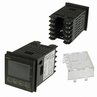
CONTROL TEMP DIGITAL HEAT/COOL
Manufacturer
Omron
Series
E5CN-Tr
Type
Temperature Controller, Digitalr
Datasheet
1.E5CN-Q2MT-500_AC100-240.pdf
(27 pages)
Specifications of E5CN-Q2MT-500 AC100-240
Input Type
RTD, Thermocouple (Multiple)
Controller Type
On/Off or Proportional (PID)
Temperature Range
Selectable, Varies By Input Type
Output Type
Voltage
Supply Voltage
100 ~ 240VAC
Size
48mm W x 48mm H (1/16 DIN)
Features
Terminal Cover
Display Type
4 Digit (2)
Lead Free Status / RoHS Status
Lead free / RoHS Compliant
Communications
-
Other names
E5CN-Q2MT-500-AC100240
E5CNQ2MT500AC100240
Z2410
E5CNQ2MT500AC100240
Z2410


Alarm Outputs
Each alarm can be independently set to one of the following 13 alarm types. The default is 2: Upper limit.
Auxiliary outputs are allocated for alarms. ON delays and OFF delays (0 to 999 s) can also be specified.
Note: For models with heater burnout, SSR failure, and heater overcurrent detection, alarm 1 will be an OR output of the alarm selected from the
value
Set
*1
*1
*1
10
11
12
13
0
1
2
3
4
5
6
7
8
9
following alarm types and the alarms for heater burnout, SSR failure, and heater overcurrent. To output only a heater burnout alarm, SSR
failure alarm, and heater overcurrent alarm for alarm 1, set the alarm type to 0 (i.e., no alarm function).
Alarm function
OFF
Upper- and lower-
limit
Upper limit
Lower limit
Upper- and lower-
limit range
Upper- and lower-
limit with standby
sequence
Upper-limit with
standby sequence
Lower-limit with
standby sequence
Absolute-value
upper-limit
Absolute-value
lower-limit
Absolute-value
upper-limit with
standby sequence
Absolute-value
lower-limit with
standby sequence
LBA
(for alarm 1 only)
PV change rate
alarm
Alarm type
http://www.ia.omron.com/
Output OFF
*5
---
---
ON
OFF
ON
OFF
ON
OFF
ON
OFF
ON
OFF
ON
OFF
ON
OFF
ON
OFF
ON
OFF
ON
OFF
ON
OFF
When X is
positive
Alarm output operation
0
0
0
0
L
L
X
L
X
SP
SP
SP
SP
SP
SP
SP
X
X
X
X
H
H
H
X
X
*2
*3
*4
ON
OFF
ON
OFF
ON
OFF
ON
OFF
ON
OFF
ON
OFF
ON
OFF
ON
OFF
When X is
negative
X
X
SP
SP
SP
SP
X
X
X
X
X
X
0
0
0
0
*1. With set values 1, 4 and 5, the upper and lower limit values can
*2. Set value: 1, Upper- and lower-limit alarm
*3. Set value: 4, Upper- and lower-limit range
*4. Set value: 5, Upper- and lower-limit with standby sequence
*5. Set value: 5, Upper- and lower-limit with standby sequence
be set independently for each alarm type, and are expressed as
“L” and “H.”
For Upper- and Lower-Limit Alarm Described Above
• Case 1 and 2
• Case 3: Always OFF
Always OFF when the upper-limit and lower-limit hysteresis
overlaps.
Always OFF when the upper-limit and lower-limit hysteresis
overlaps.
Case 1
Case 1
(c)Copyright OMRON Corporation 2008 All Rights Reserved.
H < 0, L > 0
H < 0, L > 0
⏐H⏐ < ⏐L⏐
⏐H⏐ < ⏐L⏐
L
L
H
H SP
SP
Case 2
Case 2
SP
SP
H > 0, L < 0
H > 0, L < 0
⏐H⏐ > ⏐L⏐
⏐H⏐ > ⏐L⏐
L
L H
H
Case 3 (Always OFF)
Case 3 (Always ON)
E5CN/E5CN-U
H
H
H
H SP
L
L
SP
SP
SP
SP
SP
H
H
L
L
L
L
H < 0, L > 0
H > 0, L < 0
H < 0, L > 0
H > 0, L < 0
H < 0, L < 0
H < 0, L < 0
⏐H⏐ ≥ ⏐L⏐
⏐H⏐ ≤ ⏐L⏐
⏐H⏐ ≥ ⏐L⏐
⏐H⏐ ≤ ⏐L⏐
8