E5CSV-R1T-F AC100-240 Omron, E5CSV-R1T-F AC100-240 Datasheet - Page 8
E5CSV-R1T-F AC100-240
Manufacturer Part Number
E5CSV-R1T-F AC100-240
Description
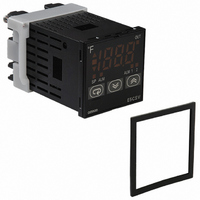
CONTROL TEMP DGTL RELAY OUT
Manufacturer
Omron
Series
E5CSVr
Type
Temperature Controller, Digitalr
Specifications of E5CSV-R1T-F AC100-240
Input Type
RTD, Thermocouple (Multiple)
Controller Type
On/Off or Proportional (PID)
Temperature Range
Selectable, Varies By Input Type
Output Type
Relay
Supply Voltage
100 ~ 240VAC
Size
48mm W x 48mm H (1/16 DIN)
Display Type
4 Digit
Lead Free Status / RoHS Status
Lead free / RoHS Compliant
Features
-
Communications
-
Other names
E5CSV-R1T-F-AC100-240
E5CSV-R1T-F-AC100240
E5CSVR1TFAC100240
Z2695
E5CSV-R1T-F-AC100240
E5CSVR1TFAC100240
Z2695


2. Operation Settings
Use the control mode switches (
trol mode. (All switches are OFF for the default settings.)
Note: The previous name Pt100 has been changed to JPt100 in ac-
For details on the position of the temperature range switch, control mode switches, and alarm mode switch, refer to page 6.
8
Note: Turn OFF the power before changing the DIP switch settings on the E5CSV. Each of the switch settings will be enabled after the power is
Function selection
ON/OFF
PID
Control
period
Direct/
reverse
opera-
tion
Input
shift
display
Temper-
ature
Sensor
selec-
tion
Temper-
ature
unit
cordance with revisions to JIS. The previous name J-DIN has
been changed to L in accordance with revisions to DIN stan-
dards.
turned ON.
PID control
ON/OFF control
2 s
20 s
Direct operation
(cooling)
Reverse operation
(heating)
Enabled
Disabled
Thermo-
couple
Platinum
resis-
tance
thermom-
eter
Multi-
input
(thermo-
couple/
platinum
resis-
tance
thermom-
eter)
° F
° C
Temperature Controllers
K, L
K, J
Pt100
JPt100
Platinum
resis-
tance
ther-
mometer
input
Thermo-
couple
input
ON
1
1
OFF
ON
2
ON
3
1
4
2
OFF
ON
5
2
E5CSV
6
3
OFF
ON
) to change the con-
3
4
OFF
ON
4
5
OFF
OFF
OFF
ON
ON
ON
5
6
OFF
6
ON
3. Alarm Modes
Select the number of the alarm mode switch
the alarm mode. (The default is 2).
Note: 1. No alarm. The alarm value (alarm operation display) will not
Rising Temperature
Upper-limit
alarm
Lower-limit
alarm
Alarm
output
Set
value
0, 9
1
2
3
4
5
6
7
8
SP
OFF
ON
2. Standby Sequence Function (The standby sequence oper-
Alarm type
Alarm function OFF
Upper- and lower-
limit
Upper-limit
Lower-limit
Upper- and lower-
limit range
Upper- and lower-
limit with standby se-
quence (See note 2.)
Upper-limit with
standby sequence
(See note 2.)
Lower-limit with
standby sequence
(See note 2.)
Absolute-value up-
per-limit
be displayed when the setting is 0 or 9 even if the selection
key is pressed.
Alarm Setting Range
X: 0 to FS (full scale); Y: Within temperature range
The value of X is the deviation setting for the SP (set point).
ates when the power is turned ON.)
Alarm output operation
OFF
OFF
OFF
OFF
OFF
OFF
OFF
OFF
OFF
ON
ON
ON
ON
ON
ON
ON
ON
Dropping Temperature
Upper-limit
alarm
Lower-limit
alarm
Alarm
output
SP
OFF
ON
X
X
X
X
X
SP
SP
SP
SP
SP
SP
SP
0
X
when changing
X
X
X
X
Y