E5CSV-R1T-F AC100-240 Omron, E5CSV-R1T-F AC100-240 Datasheet - Page 17
E5CSV-R1T-F AC100-240
Manufacturer Part Number
E5CSV-R1T-F AC100-240
Description
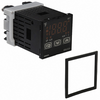
CONTROL TEMP DGTL RELAY OUT
Manufacturer
Omron
Series
E5CSVr
Type
Temperature Controller, Digitalr
Specifications of E5CSV-R1T-F AC100-240
Input Type
RTD, Thermocouple (Multiple)
Controller Type
On/Off or Proportional (PID)
Temperature Range
Selectable, Varies By Input Type
Output Type
Relay
Supply Voltage
100 ~ 240VAC
Size
48mm W x 48mm H (1/16 DIN)
Display Type
4 Digit
Lead Free Status / RoHS Status
Lead free / RoHS Compliant
Features
-
Communications
-
Other names
E5CSV-R1T-F-AC100-240
E5CSV-R1T-F-AC100240
E5CSVR1TFAC100240
Z2695
E5CSV-R1T-F-AC100240
E5CSVR1TFAC100240
Z2695


9. Use the product within the rated load and power supply.
10.Use a switch, relay, or other contact so that the power supply volt-
11.When using PID operation (self-tuning), turn ON the power supply
12.Design the system (e.g., control panel) to allow for the 2 seconds
13.A switch or circuit breaker should be provided close to this unit.
14.Approximately 30 minutes is required for the correct temperature
15.Be sure that the platinum resistance thermometer type and the
16.When extending the thermocouple lead wires, always use com-
17.When drawing out the Temperature Controller from the case, do
18.When drawing out the Temperature Controller from the case to
19.When drawing out the Temperature Controller from the case, turn
20.Static electricity may damage internal components. Always touch
21.Do not use paint thinner or similar chemical to clean with. Use
22.Use tools when separating parts for disposal. Contact with the
age reaches the rated voltage within 2 seconds. If the applied
voltage is increased gradually, the power supply may not be reset
or malfunctions may occur.
to the load (e.g., heater) at the same time or before turning the
power supply to the Temperature Controller ON. If power is turned
ON for the Temperature Controller before turning ON power sup-
ply to the load, self-tuning will not be performed properly and opti-
mum control will not be achieved.
of delay required for the Temperature Controller's output to stabi-
lize after the power is turned ON.
The switch or circuit breaker should be within easy reach of the
operator, and must be marked as a disconnecting means for this
unit.
to be displayed after turning the power supply to the Temperature
Controller ON. Turn the power supply ON at least 30 minutes prior
to starting control operations.
input type set on the Temperature Controller are the same.
pensating conductors suitable for the type of thermocouple. Do
not extend the lead wires on a platinum resistance thermometer.
Use only low-resistance wire (5 Ω max. per line) for lead wires and
make sure that the resistance is the same for all three wires.
not apply force that would deform or alter the Temperature Con-
troller.
replace the Temperature Controller, check the status of the termi-
nals. If corroded terminals are used, contact faults with the termi-
nals may cause the temperature inside the Temperature
Controller to increase, possibly resulting in fire. If the terminals
are corroded, replace the rear case as well.
the power supply OFF first, and absolutely do not touch the termi-
nals or electronic components or apply shock to them. When
inserting the Temperature Controller, do not allow the electronic
components to come into contact with the case.
grounded metal to discharge any static electricity before handling
the Temperature Controller. When drawing out the Temperature
Controller from the case, do not touch the electronic components
or patterns on the board with your hand. Hold the Temperature
Controller by the edge of the front panel when handling it.
standard grade alcohol.
sharp internal parts may cause injury.
■ Precautions for Correct Use
Service Life
Use the Temperature Controller within the following temperature and
humidity ranges:
If the Controller is installed inside a control board, the ambient tem-
perature must be kept to under 55° C, including the temperature
around the Controller.
The service life of electronic devices like Temperature Controllers is
determined not only by the number of times the relay is switched but
also by the service life of internal electronic components. Component
service life is affected by the ambient temperature: the higher the
temperature, the shorter the service life and, the lower the tempera-
ture, the longer the service life. Therefore, the service life can be
extended by lowering the temperature of the Temperature Controller.
When two or more Temperature Controllers are mounted horizontally
close to each other or vertically next to one another, the internal tem-
perature will increase due to heat radiated by the Temperature Con-
trollers and the service life will decrease. In such a case, use forced
cooling by fans or other means of air ventilation to cool down the
Temperature Controllers. When providing forced cooling, however, be
careful not to cool down the terminals sections alone to avoid mea-
surement errors.
Measurement Accuracy
When extending or connecting the thermocouple lead wire, be sure
to use compensating wires that match the thermocouple type. Do not
extend the lead wire of the platinum resistance thermometer. If the
lead wire of the platinum resistance thermometer must be extended,
be sure to use wires that have low resistance and keep the resis-
tance of the three lead wires the same.
Mount the Temperature Controller so that it is horizontally level.
If the measurement accuracy is low, check whether the input shift
has been set correctly.
Waterproofing
The degree of protection is as shown below. Sections without any
specification on their degree of protection or those with IP@0 are not
waterproof.
Temperature:
Humidity:
Front panel: IP66, rear case: IP20, terminals: IP00
Temperature Controllers
–
25% to 85%
10 to 55° C (with no icing or condensation)
E5CSV
17