LCBS-8-01 Richco Plastic Co, LCBS-8-01 Datasheet - Page 6
LCBS-8-01
Manufacturer Part Number
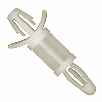
LCBS-8-01
Description
LOCKING BOARD SUPPORT 1/2"
Manufacturer
Richco Plastic Co
Series
LCBSr
Specifications of LCBS-8-01
Holding Type
Arrowhead, Snap Lock
Length
1.229" (31.22mm)
Between Board Height
0.500" (12.70mm) 1/2"
Mounting Type
Arrowhead, Snap-Lock, Winged
Support Hole Diameter
0.156" (3.96mm) 5/32"
Support Panel Thickness
0.062" (1.57mm) 1/16"
Mounting Hole Diameter
0.187" (4.75mm) 3/16"
Mounting Panel Thickness
0.031 ~ 0.078" (0.79 ~ 1.98mm)
Overall Length
12.7mm
Spacer Material
Nylon
External Width
7.1mm
Spacing Height
12.7mm
Body Diameter
4.75mm
Spacer Style
PC Board
Color
Natural
Diameter
0.28 in.
Diameter, Mounting Hole
0.156 in. ±0.003 in. Dia. Hole in a 0.82 in. Thick Board, 0.187 in. ±0.003 in. Dia. Hole in a 1⁄16 in. (Nominal) Thick Panel⁄Chassis
Size, Thread
7⁄32
Lead Free Status / RoHS Status
Lead free / RoHS Compliant
Lead Free Status / RoHS Status
Lead free / RoHS Compliant, Lead free / RoHS Compliant
Other names
LCBS-8
RP430
RP430


ABSOLUTE MAXIMUM RATINGS*
Voltage on Any Pin Relative to Ground
Operating Temperature
Storage Temperature
Soldering Temperature
* This is a stress rating only and functional operation of the device at these or any other conditions above those
RECOMMENDED DC OPERATING CONDITIONS
DC ELECTRICAL CHARACTERISTICS
*Unless otherwise noted.
CAPACITANCE
DS1202, DS1202S
032697 6/11
PARAMETER
Supply Voltage
Logic 1 Input
Logic 0 Input
Logic 0 Input
PARAMETER
Input Leakage
I/O Leakage
Logic 1 Output
Logic 1 Output
Logic 0 Output
Logic 0 Output
Active Supply Current
Active Supply Current
Timekeeping Current
Timekeeping Current
Leakage Current
Leakage Current
PARAMETER
Input Capacitance
I/O Capacitance
Crystal Capacitance
indicated in the operation sections of this specification is not implied. Exposure to absolute maximum rating
conditions for extended periods of time may affect reliability.
SYMBOL
V
V
V
V
V
I
I
I
I
C
V
I
I
V
V
I
CC1
CC1
CC2
CC2
C
I
CC
CC
LO
C
CC
LI
OH
OH
OL
OL
IH
I/O
IL
IL
X
I
SYMBOL
SYMBOL
V
CONDITION
V
V
V
V
V
V
V
V
V
V
V
CC
CC
CC
CC
CC
CC
CC
CC
CC
CC
CC
CC
=2.0V
=5V
=2V
=5V
=2V
=5V
=2V
=5V
=2V
=5V
=2V
=5V
–0.3V to +7.0V
0 C to 70 C
–55 C to +125 C
260 C for 10 seconds
–0.3
–0.3
MIN
MIN
2.0
2.0
1.6
2.4
TYP
10
5
6
TYP
TYP
(0 C to 70 C; V
MAX
V
CC
MAX
MAX
+500
+500
+0.3
+0.8
100
100
5.5
0.4
0.4
0.4
1.2
0.3
1
+0.3
UNITS
pF
pF
pF
CC
UNITS
UNITS
mA
mA
nA
nA
V
V
V
V
V
V
V
V
= 2.0 to 5.5V*)
A
A
A
A
(0 C to 70 C)
(t
A
NOTES
NOTES
NOTES
= 25 C)
10
10
1
1
1
1
6
6
2
2
3
3
5
5
4
4
Related parts for LCBS-8-01
Image
Part Number
Description
Manufacturer
Datasheet
Request
R

Part Number:
Description:
CBS LOCKING NYLON 3/8"
Manufacturer:
Richco Plastic Co
Datasheet:
Part Number:
Description:
CBS LOCKING NYLON 1/2"
Manufacturer:
Richco Plastic Co
Datasheet:
Part Number:
Description:
CBS LOCKING NYLON 3/16"
Manufacturer:
Richco Plastic Co
Datasheet:
Part Number:
Description:
CBS LOCKING NYLON 1/4"
Manufacturer:
Richco Plastic Co
Datasheet:
Part Number:
Description:
CBS LOCKING NYLON 5/16"
Manufacturer:
Richco Plastic Co
Datasheet:
Part Number:
Description:
CBS LOCKING NYLON 7/16"
Manufacturer:
Richco Plastic Co
Datasheet:
Part Number:
Description:
CBS LOCKING NYLON 5/8"
Manufacturer:
Richco Plastic Co
Datasheet:
Part Number:
Description:
CBS LOCKING NYLON 7/8"
Manufacturer:
Richco Plastic Co
Datasheet:
Part Number:
Description:
CBS LOCKING NYLON 1 1/8"
Manufacturer:
Richco Plastic Co
Datasheet:
Part Number:
Description:
CBS LOCKING NYLON 1 3/8"
Manufacturer:
Richco Plastic Co
Datasheet:
Part Number:
Description:
CBS LOCKING FR NYL 1/2"
Manufacturer:
Richco Plastic Co
Datasheet:
Part Number:
Description:
CBS LOCKING NYLON 3/4"
Manufacturer:
Richco Plastic Co
Datasheet:
Part Number:
Description:
CBS LOCKING NYLON 1"
Manufacturer:
Richco Plastic Co
Datasheet:
Part Number:
Description:
CBS LOCKING NYLON 1 1/4"
Manufacturer:
Richco Plastic Co
Datasheet:
Part Number:
Description:
CLAMP VINYL-DIPPED 15/32X38"
Manufacturer:
Richco Plastic Co
Datasheet: