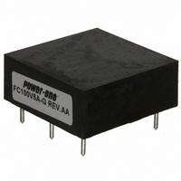
FC100V5A POWER ONE, FC100V5A Datasheet - Page 11

FC100V5A
Manufacturer Part Number
FC100V5A
Description
FILTER 5 AMP PC MOUNT
Manufacturer
POWER ONE
Series
FCr
Datasheet
1.FC100V5A-G.pdf
(41 pages)
Specifications of FC100V5A
Filter Type
Power Line
Voltage - Rated
100V
Current
5A
Mounting Type
Through Hole
Termination Style
PCB Pins
Operating Temperature Min Deg. C
-40C
Operating Temperature Max Deg. C
85C
Rad Hardened
No
Lead Free Status / RoHS Status
Contains lead / RoHS non-compliant
Inductance
-
Lead Free Status / RoHS Status
Contains lead / RoHS non-compliant, Not Compliant
Other names
179-2178
Available stocks
Company
Part Number
Manufacturer
Quantity
Price
Part Number:
FC100V5A
Manufacturer:
POWER-O
Quantity:
20 000
Part Number:
FC100V5A
Quantity:
55
Thermal Considerations
Because of low series internal DC resistance, the
F4810/F2410 filters generally do not require airflow
and/or derating to ambient temperatures up to 85 ˚C,
if placed and interconnected as described below.
Good thermal design is consistent with appropriate
placement to gain additional heat exchange through
the I/O pins to the system board. For high
temperature operation in low airflow environments,
use of 1-2 oz copper for the external connection
pads and provision for some extra copper at all four
I/O pins is encouraged. Thermal derating data shown
were taken on special thermal board with each input
and output pin connected to 0.5 sq. in pad of 2 oz
copper.
To check filter thermal characteristic in an actual
system environment, attach a thermocouple to the
top of differential inductor, L2; it is the INDUCTOR
closest to OUT+ pin.
The maximum temperature at this test point should
not exceed 120 ˚C, and a minimum of 5-10 ˚C
headroom is suggested for better reliability.
MCD10059 Rev. 1.1, 21-Jan-10
V
V
IN +
IN -
For further information
regarding connection of CM
capacitors and other
pertinent layout and EMC
information, please refer to
the Layout Considerations
and EMI Considerations
Application notes.
12A
F1
P1
P2
+48V
-48V
Input Filter
F4810
(Top View)
+Vout
-Vout
P3
P4
F2410 & F4810, 0-45V/0-80V, 10 Amps, SMT Mount
+
C1
Fig. 5: F4810 – Typical application
F & FC Series DC-DC Converter Input Filters
Page 11 of 41
C2
C3
Vin (+)
ON/OFF
Vin (+)
ON/OFF
Vin (-)
Vin (-)
A typical application schematic is shown in Fig. 5.
Either filter can be used to power one or more
converters. Maximum filter output current should be
limited 10 A - or less - depending upon system
thermal environment.
The required filter current drawn by the converter
loads, I
connected converters:
I
where:
For applications requiring a filter current greater than
10 A, divide the converters into smaller groups and
use multiple filters. Do not connect filters in parallel.
REQ’d
P
i,OUT
I
REQ’d
(filter) = Σ[P
QmaX
QmaX
V
(converter)
(Top View)
(Top View)
η
Converter
Converter
REQ’d
IN, min
i, min
Converter
(Top View)
Converter
(Top View)
DC-DC
DC-DC
(filter)
C4
C6
TM
TM
(Filter), will be the sum of the loads of all
C5
Series
C7
Series
i,OUT
SENSE (+)
SENSE (+)
SENSE (-)
SENSE (-)
maximum required filter current
converter output power, i=1, 2…
= V
I
converter input voltage
converter minimum efficiency, i=1,
2,…
i,OUT
Vout (+)
Vout (+)
Vout (-)
Vout (-)
TRIM
TRIM
/(V
i,OUT
(converter)
IN, min
(converter) *
* η
C9
C8
i, min
www.power-one.com
)]
Rload1
Rload2
[A]


