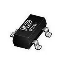
BAP64-05 NXP Semiconductors, BAP64-05 Datasheet - Page 4

BAP64-05
Manufacturer Part Number
BAP64-05
Description
Two planar PIN diodes in common cathode configuration in a SOT23 small plastic SMD package
Manufacturer
NXP Semiconductors
Type
Attenuator/Switchr
Datasheet
1.BAP64-05.pdf
(8 pages)
Specifications of BAP64-05
Configuration
Dual Common Cathode
Forward Current
100mA
Forward Voltage
1.1V
Power Dissipation
250mW
Operating Temperature Classification
Military
Reverse Voltage
175V
Package Type
SOT-23
Mounting
Surface Mount
Maximum Series Resistance @ Minimum If
40@0.5mAOhm
Maximum Series Resistance @ Maximum If
1.35@100mAOhm
Typical Carrier Life Time
1.55us
Operating Temperature (max)
150C
Operating Temperature (min)
-65C
Pin Count
3
Applications Frequency Range
SHF
Lead Free Status / RoHS Status
Compliant
Available stocks
Company
Part Number
Manufacturer
Quantity
Price
Company:
Part Number:
BAP64-05
Manufacturer:
NXP
Quantity:
51 000
Company:
Part Number:
BAP64-05
Manufacturer:
NXP
Quantity:
3 200
Part Number:
BAP64-05
Manufacturer:
PHI
Quantity:
20 000
Company:
Part Number:
BAP64-05W
Manufacturer:
NXP
Quantity:
15 000
Company:
Part Number:
BAP64-05W
Manufacturer:
PANASONIC
Quantity:
36 000
Part Number:
BAP64-05W
Manufacturer:
CJ/长电
Quantity:
20 000
Company:
Part Number:
BAP64-05W115
Manufacturer:
NXP Semiconductors
Quantity:
102 101
NXP Semiconductors
GRAPHICAL DATA
1999 Aug 19
handbook, halfpage
handbook, halfpage
handbook, halfpage
Silicon PIN diode
f = 100 MHz; T
(1) I
(2) I
Diode inserted in series with a 50 stripline circuit
and biased via the analyzer Tee network.
T
Fig.4
amb
S 21
S 21
(dB)
(dB)
(Ω)
10
r D
10
−1
−1
−2
−2
−3
−3
−4
−4
−5
−5
F
F
= 25 C.
10
Fig.2
−1
10
0
0
2
2
1
= 100 mA.
= 10 mA.
2
0.5
0.5
−1
Insertion loss (S
function of frequency; typical values.
j
Forward resistance as a function of
forward current; typical values.
= 25 C.
1
1
1
(3) I
(4) I
1.5
1.5
(1)
(1)
(3)
(4)
(3)
(4)
F
F
21
= 1 mA.
= 0.5 mA.
2
(2)
(2)
) of the diode as a
2
2
10
I F (mA)
2.5
2.5
f (GHz)
f (GHz)
MCD769
MCD771
MCD771
10
3
3
2
4
handbook, halfpage
handbook, halfpage
f = 1 MHz; T
Fig.3
Diode zero biased and inserted in series with a 50 stripline circuit.
T
Fig.5
S 21
amb
(dB)
(fF)
C d
600
400
200
−10
−20
−30
= 25 C.
0
0
2
0.5
0
Diode capacitance as a function of reverse
voltage; typical values.
Isolation (S
of frequency; typical values.
j
= 25 C.
4
1
21
1.5
8
2
) of the diode as a function
12
2
Product specification
2.5
16
BAP64-05
V R (V)
f (GHz)
MCD770
MCD772
20
3


