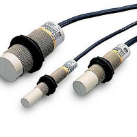
E2K-X4ME2 5M Omron, E2K-X4ME2 5M Datasheet - Page 12

E2K-X4ME2 5M
Manufacturer Part Number
E2K-X4ME2 5M
Description
Proximity Sensors E2K-X4ME2 W/ 5 METER CABLE
Manufacturer
Omron
Series
E2K-Xr
Type
Proximity Sensorr
Specifications of E2K-X4ME2 5M
Proximity Sensor Sensing Distance
4mm
Proximity Sensor Sensing Distance Range
2 to 7mm
Proximity Sensor Switching Mode
NC
Mounting
Panel
Operating Temp Range
-25C to 70C
Operating Temperature Classification
Commercial
Operating Supply Voltage (min)
10V
Operating Supply Voltage (typ)
12/15/18/24V
Operating Supply Voltage (max)
30V
Pin Count
3
Output Type
NPN
Maximum Operating Temperature
+ 70 C
Supply Voltage
12 VDC to 24 VDC
Supply Current
15 mA
Output Voltage
1 V
Operating Supply Voltage
10 VDC to 30 VDC
Mounting Style
Panel
Sensing Distance
4 mm
Minimum Operating Temperature
- 25 C
Current Rating
200 mA
Features
Permits non-contact detection of metallic and non-metallic objects
Voltage Rating
24 VDC
Lead Free Status / RoHS Status
Supplier Unconfirmed
●Wiring Considerations
AND/OR Connections for Proximity Sensors
Note: When AND/OR connections are used with Proximity Sensors, the effects of erroneous pulses or leakage current may prevent use. Verify that there are no
DC 2-Wire
AC 2-wire
Model
problems before use.
connection
AND (series
connection)
OR (parallel
connection)
AND (series
connection)
OR (parallel
connection)
Type of
http://www.ia.omron.com/
(A)
(A)
+
+
-
+
X
-
1
-
+
(B)
(B)
Connection
X
1
Load
Load
Load
V
X
X
2
L
2
Load
X
Load
Load
Load
1
X
X
X
2
1
2
V
Vs
S
Vs
V
V
V
Proximity Sensors Technical Guide
≥ 100V
S
S
S
Keep the number of connected Sensors (N) within the range of the following
equation.
V
It is possible, however, that the indicators may not light correctly and error
pulses (of approximately 1 ms) may be generated because the rated power
supply voltage and current are not supplied to individual Proximity Sensors.
Verify that this is not a problem before operation.
Keep the number of connected Sensors (N) within the range of the following
equation.
N × i ≤ Load reset current
Example: When an MY (24-VDC) Relay is used as the load, the maximum number
of Sensors that can be connected is 4.
<TL-NY, TL-MY, E2K-@MY@, TL-T@Y>
The above Proximity Sensors cannot be used in a sereis connection. If need-
ed, connect through relays.
<E2E-X@Y>
For the above Proximity Sensors, the voltage VL that can be applied to the
load when ON is V
both 100 VAC and 200 VAC.
The load will not operate unless V
This must be verified before use.
When using two or more Sensors in series with an AND circuit, the limit is three
Sensors. (Be careful of the VS value in the diagram at left.)
In general it is not possible to use two or more Proximity Sensors in parallel
with an OR circuit.
A parallel connection can be used if A and B will not be operated simulta-
neously and there is no need to hold the load. The leakage current, however,
will be n times the value for each Sensor and reset failures will frequently oc-
cur.
("n" is the number of Proximity Sensors.)
If A and B will be operated simultaneously and the load is held, a parallel con-
nection is not possible.
If A and B operate simultaneously and the load is held, the voltages of both A
and B will fall to about 10 V when A turns ON, and the load current will flow
through A causing random operation. When the sensing object approaches B,
the voltage of both terminals of B is too low at 10 V and the switching element
of B will not operate. When A turns OFF again, the voltages of both A and B
rise to the power supply voltage and B is finally able to turn ON.
During this period, there are times when A and B both turn OFF (approximately
10 ms) and the loads are momentarily restored. In cases where the load is to
be held in this way, use a relay as shown in the diagram at left.
S
N : Number of Sensors that can be connected
V
V
N: Number of Sensors that can be connected
i: Leakage current of Proximity Sensor
- N × V
R
S
: Power voltage
: Residual output voltage of Proximity Sensor
(c)Copyright OMRON Corporation 2007 All Rights Reserved.
R
≥ Operating load voltage
L
= V
S
- (Output residual voltage × Number of Sensors), for
Description
L
is higher than the load operating voltage.
C-6


