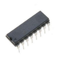
PBL3717A STMicroelectronics, PBL3717A Datasheet

PBL3717A
Specifications of PBL3717A
Available stocks
Related parts for PBL3717A
PBL3717A Summary of contents
Page 1
... Two PBL3717As and few external components form a complete stepper motor drive subsystem. The raccomended operating ambient temperature ranges is from The PBL3717A is supplied lead Pow- erdip package. July 2003 STEPPER MOTOR DRIVER CURRENT ORDER CODE : PBL3717A ...
Page 2
... PBL3717A PIN FUNCTIONS N Name 1 UTPUT B 2 PULSE TIME 3 SUPPLY VOLTAGE B 4 GROUND 5 GROUND 6 LOGIC SUPPLY 7 INPUT 1 8 PHASE 9 INPUT 0 10 COMPARATOR INPUT 11 REFERENCE 12 GROUND 13 GROUND 14 SUPPLY VOLTAGE A 15 OUTPUT A 16 SENSE RESISTOR TRUTH TABLE Input 0 (pin 9) Input 1 (pin 2/11 Output Connection (with pin 15). The output stage is a "H" bridge formed by four transistors and four diodes suitable for switching applications ...
Page 3
... Reference Input Voltage r I Output Current (DC operation Storage Temperature stg T Operating Junction Temperature j THERMAL DATA Symbol R Thermal Resistance Junction-pins th j-case R Thermal Resistance Junction-ambient* th j-amb 2 * Soldered thick 20 cm P.C. board copper area. Parameter Parameter PBL3717A Value Unit 1.2 A – 150 C 150 C Value Unit 11 C/W 40 ...
Page 4
... PBL3717A ELECTRICAL CHARACTERISTICS (refer to the test circuit V = 36V Symbol Parameter V Supply Voltage (pin 3, 14 Logic Supply Voltage (pin Logic Supply Current (pin Reference Input Current (pin 11) R LOGIC INPUTS V Input Low Voltage (pins Input High Voltage (pin Low Voltage Input Current (pins ...
Page 5
... Figure 1 : Test and Application Circuit Figure 2 : Waveforms with MA Regulating (phase = 0) PBL3717A 5/11 ...
Page 6
... PBL3717A Figure 3 : Two Phase Bipolar Stepper Motor Driver Figure 4 : P.C. Board and Component Layout of the Circuit of fig scale) 6/11 ...
Page 7
... Figure 5 : Input and Output Sequences for Half Step and Full Step Operation APPLICATION INFORMATIONS Figure 3 shows a typical application in which two PBL3717A control a two phase bipolar stepper mo- tor. Programming The logic inputs I and I set at three different levels 0 1 the amplitude of the current flowing in the motor winding according to the truth table of page 2. A high level on the " ...
Page 8
... Source Saturation Voltage versus Output Current (recircuit period) Figure 8 : Sink Saturation Voltage versus Output Current 8/ Filter To reduce EMI and chopping losses in the motor a low pass L -C filter can be inserted across the out- puts of the PBL3717A as shown on the following pic- ture etc. 2 Figure 7 : Figure ...
Page 9
... The diagram of fig. 11 shows the maximum dissipa- ble power P and the R tot th j-amb side " " of two equal square copper areas having a thichkness of 35 (see fig. 10). Figure 11 : Max. Dissipable Power and Junction- Ambient Thermal Resistance versus size "a" PBL3717A as a function of the 9/11 ...
Page 10
... PBL3717A mm DIM. MIN. TYP. MAX. a1 0.51 B 0.85 1.40 b 0.50 b1 0.38 0.50 D 20.0 E 8.80 e 2.54 e3 17.78 F 7.10 I 5.10 L 3.30 Z 1.27 10/11 inch MIN. TYP. MAX. 0.020 0.033 0.055 0.020 0.015 0.020 0.787 0.346 0.100 0.700 0.280 0.201 0.130 0.050 OUTLINE AND MECHANICAL DATA ...
Page 11
... STMicroelectronics – Printed in Italy – All Rights Reserved Australia - Brazil - Canada - China - Finland - France - Germany - Hong Kong - India - Israel - Italy - Japan - Malaysia - Malta - Morocco - Singapore - Spain - Sweden - Switzerland - United Kingdom - United States. STMicroelectronics GROUP OF COMPANIES http://www.st.com PBL3717A 11/11 ...


